Hi,
Joachim, are You sure to have picked a P-Type MOSFET and not a N-Type?
Zetex nomenclatura is straightforward as ZVNs beeing N-Types and ZVPs beeing P-Types, but beeing 4-eyed elder statesmen, we sometimes have difficulties reading tiny letters")
It also seems that the current symmetry is a bit more sensitive to the resistor relationship than with bipolar output transistors.
jauu
Calvin
Joachim, are You sure to have picked a P-Type MOSFET and not a N-Type?
Zetex nomenclatura is straightforward as ZVNs beeing N-Types and ZVPs beeing P-Types, but beeing 4-eyed elder statesmen, we sometimes have difficulties reading tiny letters
It also seems that the current symmetry is a bit more sensitive to the resistor relationship than with bipolar output transistors.
jauu
Calvin
here we go...
Very nice.
When I get back to the states I will try this out

I am sure i took the P-channel, i measure each semi before i put it in the system.
Being shortsighted i spied a P.
Yes, the resistor balance is more critical because small changes in bias voltage make big changes in idle.
>I will be back from Pro Light and Sound tomorrow and can continue on monday.
It should be possible to fix it.
Being shortsighted i spied a P.
Yes, the resistor balance is more critical because small changes in bias voltage make big changes in idle.
>I will be back from Pro Light and Sound tomorrow and can continue on monday.
It should be possible to fix it.
I played around a bit with the MosFet buffer but no success at this time.
I have a bad cold and i am occupied with other things so this has to wait.
On the other hand i am 100% satisfied with the BJT version. It worked right away, is stable, measures very well and sounds great.
I had one of the most critical listeners here, Martina Schöner. We listened to very dense classical and delicate folk from the 60th and she was impressed about enormous energy and warmth combined with high resolution and speed. She also commended positive on the physical presence of the sound. Voices and instruments really appear like real.
Hi,
with the chosen MOSFETs the Vgs is probabely too close to the Vgs(th) and the MOSFETs work in a rather ´curved´ range of the Vgs/Id curve.
Things might improve with lower Idss MOSFETs. A ZVP3306F simmed slightly better than its stronger brother ZVP2106G.
The tolerances of the MOSFETs off of the shelf are quite large in this respect.
I assumed in one of the first posts that the MOSFETs needed to be matched also, not just the JFETs. Vbe of bipolars is better defined and the Vbe/Ie curve more linear. This seems to pay off in less hassle with tolerances and to get the circuit running.
I assume that the identical pos and neg branches, the JFET-cascodes, the feedback loop and modulation define the sonic character of this circuit mainly.
The Q of bipolar vers. MOSFET as output transistor is probabely of nil importance here.
jauu
Calvin
Hi,
seems an artefact of former sims made its way through to publishing
1uH to 2.2uH should be fine for most load conditions. It should stabilize against oscillation into common capacitive loads already without the input LP filter.
The filter then just be used to prevent RF to enter the circuit and to taylor the amplitude response as desired.
jauu
Calvin
Ok, I am convinced... I am on to it http://www.diyaudio.com/forums/anal...preamp-buffers-simple-idea-6.html#post3445542
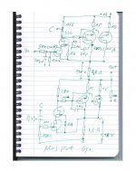
Left side schematic.... will try it soon.
Left side schematic.... will try it soon.
Hi,
just had a quick glance on that lil´Bug on my way to HighEnd Munic.
Think the FZT has a different pinout. Seems to me You twisted base and emitter.
jauu
Calvin
ps. Joachim, I assume You´re also attending the show. I´d be happy if You drop by at our booth in Hall3, C06, or I´d like to drop by at Your booth which would be ....??
Thanks, Calvin. Small wonder that you would notice. Have fun at HighEnd Munich.
Indeed, I twisted base and emitter plus one other small sin. I'll try again, maybe I can just flip the FZT upside down and move the 150 pF cap to its proper location. I'm not trying to win a beauty contest anyway.
Auch, jauu
grufti
Indeed, I twisted base and emitter plus one other small sin. I'll try again, maybe I can just flip the FZT upside down and move the 150 pF cap to its proper location. I'm not trying to win a beauty contest anyway.
Auch, jauu
grufti
Last edited:
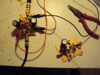
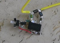
Calvin, many thanks for the nice buffer! Its great, I just implemented in my Paradise phono stage at the output, and thats shown here: http://www.diyaudio.com/forums/analogue-source/218625-paradise-builders-215.html#post3482479
Its a variant of post 52 right side, a couple transistors and resistors changed. hope you like my home-made output inductors
Its a variant of post 52 right side, a couple transistors and resistors changed. hope you like my home-made output inductors
- Home
- Source & Line
- Analog Line Level
- Preamp-Buffers - simple idea