Hi Azmi,
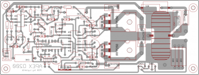
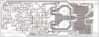
I've traced the circuit for the protection. It uses 2 of the NAND gates(pins 1 to 6) for shutdown control, the input for the pins 1 and 2 of 74HC00 (encircled in the attached pic) is normally "low", when there's a voltage across the current sensing resistor, pins 1 and 2 will go "high", resulting pin 6 to output high then triggers the SD pin of IR2110.
But there's no delay for the trigger, the 47uf connected in pin 5 is only for startup delay.
I'm afraid the protection will loop fast (assuming current sensing in speaker out works) and might lead to mosfet destruction.
Protect have delay with 2k2 and 220pF for activate, 47uF and 10k for startup delay is also for protect release delay.
Regards
I am no longer building this amp,its very complicated so im going with an apex b500.
It seems as this thread lost popularity when i stopped posting
that's too bad,because you contributed so much to this thread...
.
i have decided to try this amplifier,i have read this thread from the page 43 up to here but will not start assembling it untill i read it from a page 1.
its one heck of a chalenge to build these ,so make sure you are prepared not like me who put it aside since it requires too many partsthat's too bad,because you contributed so much to this thread...
.
i have decided to try this amplifier,i have read this thread from the page 43 up to here but will not start assembling it untill i read it from a page 1.
there are not so many parts in this amplifier,but main thing that can be an opsticle is if it doesn´ t work from first plugging in i am in trouble because only thing that i can do is to measure the frequency and current/voltage by my DMM - i also don´t have osciloscope. all i can do is to read this thread and hope for the best. more than a few people did it,i hope to be one of them...
yep know that feeling,it happens a lot to me,if it dosent work no one can help you,i tried building many amps but only one worked,for the others people didnt know how to help methere are not so many parts in this amplifier,but main thing that can be an opsticle is if it doesn´ t work from first plugging in i am in trouble because only thing that i can do is to measure the frequency and current/voltage by my DMM - i also don´t have osciloscope. all i can do is to read this thread and hope for the best. more than a few people did it,i hope to be one of them...

i have built 10 amplifiers up till now,all ab and one b-class and all of them work well as they should. d-class is something a bit new to me and more demanding one-from tehnical point of view and from needed equippment point of view.
i will try it,so we will see what will happen´.
i will try it,so we will see what will happen´.
use main supply in series with bulb when first time power on . btw if your component is the same what apex showing and mount them correctly, dont be rush, check every component and trace, im sure this amp will work nicely. most ppls do modified with another value component because they dont have exactly component listed by apex, so there is the problem, when u want build class D amp who already testing and running, you need to have commitment for all part list with the same value and type.
p/s - there is no shortcut to make it more easy
. btw if your component is the same what apex showing and mount them correctly, dont be rush, check every component and trace, im sure this amp will work nicely. most ppls do modified with another value component because they dont have exactly component listed by apex, so there is the problem, when u want build class D amp who already testing and running, you need to have commitment for all part list with the same value and type.p/s - there is no shortcut to make it more easy
use main supply in series with bulb when first time power on
p/s - there is no shortcut to make it more easy
that is exactly the way i plan to do it. all APEX amplifiers i did up till now worked at first plug-in unless i made a mistake. after removing mistake they are working all right and with no problems at all.
i did one smps,and there i used that "trick" with light bulb,that is what i will use now too. when ever i did ab or b-class amp i used 20W 17R resistors in series with power supply rails just to make sure that the amp works fine.
thanks for moral support man!
PetruV,i will make pcb as APEX suggested,not on perfboard.
hope i will soon write here and post some pictures

have you compared gate charge of those two transistors at output? i am not suggesting anything since ia haven´t checked that eather yet but that would be the most important thing...
another thing - if you can make pads a bit wider,that narrow will be weak to the soldering temperature.
otherwise it looks ok to me.
another thing - if you can make pads a bit wider,that narrow will be weak to the soldering temperature.
otherwise it looks ok to me.
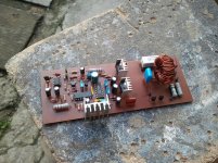
My new PCB
Tested my new pcb today. Gives a very high siren noise after 2 seconds when I touch the inputs.
tested +/- 5.6, ok.
12v ok
5v ok
used irf540n with +/-30 volts
When I checked outputs with the meter it says 106Khz
All worked well with Apex's D200 board.
But what could be the reason for this siren sound in my board?
regards.
Attachments
Tested my new pcb today. Gives a very high siren noise after 2 seconds when I touch the inputs.
tested +/- 5.6, ok.
12v ok
5v ok
used irf540n with +/-30 volts
When I checked outputs with the meter it says 106Khz
All worked well with Apex's D200 board.
But what could be the reason for this siren sound in my board?
regards.
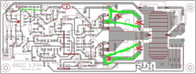
Change some tracks.
Regards
Attachments
yep know that feeling,it happens a lot to me,if it dosent work no one can help you,i tried building many amps but only one worked,for the others people didnt know how to help me
hai petruv, i think you have problem with the pcb, look like it finish with bad result. many diy'er get that result in their work, but after many experiment and learning what other people do with good result i believe success will be with you
1. make sure the pcb result free from short between track, crack or lost connection cek with ohm meter.
2. make sure you use a good quality component since now there is many counterfit component in the market, i am had that when i build APEX H900 amp, the ic NE5532 was bad quality or counterfit
3. always learn your soldering skill that have good result/ max joint, make sure there is no short between track or dry joint
4. cek once again then test with supply for fist time, before that place 20ohm/10W resistor on + rail and -rail or place 60W/220v bulp series with primer tranformer, if there is any trouble will save your valuable component
5. if there any problem with the result, share with us, many people in this forum will help you
regard
Last edited:
- Home
- Amplifiers
- Class D
- Class D Amp with LM566, LM393 and 2XIRF530