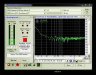
When uplugged you should see only noise level of the ADC when calibrating RMAA. When plugged but the DAC is not playing you will see the noise of DAC - a few dB louder in my case. You may see something like -60dB or quieter. When playing you should keep the volume high but not too much: the sound easily gets distorted at some level. I/V opamps gave me ~ -3dB through the stock resistors in the final stage and RCA output. When using TPA6120 I get the -8.8dB. Making the volume higher will distort the signal. The option is to slightly lower the feedback at the I/V stage to match the volumes. Compare the results with different cards.OK. I have disabled "Wave" and enabled/default "Line in" before measurements. Loop in between output - Line in. I could see that Line in were active (level meter worked). I will verify again.
The depth and transparency is what changes the most. Sound becomes more thin and clean. May sound like a loudness curve for some people, but it's something more. A lot of new sound details are now always present, but some still change. The tcxo I use really makes a mess to the PSU line. Change the line and the next becomes messed up. Lot of filtering. External battery is an option. I find the tcxo to be much, much more sensitive to the power supply quality than the opamps.I have finished now the battery powered oscillator. A big increase in quality. The fidelity is just exceptional, but the most impressive now is the sound stage. It gets more depth and both the instruments and voices are very well separated in space. The speakers are just transparent. The sound is in the room and fill it. Very impressive!
Tens (or hundreds) of new caps will arrive soon. Another cap was blown away, wrong polarity ;-)
I have took a closer look to my measurement environments. It looks like my Line in on the card is quite dead... Maybe it happen something with the IN stage of the board in those mod processes. I do not care about this aspect as I do not use that option anymore. Only problem is with the measurements now...
If I will find a way, I will try to measure again... I concentrate my self now to finish this last mod. I have experienced before that slow variation of the battery (discharging) tension it have no influence on the quality of the sound. It looks like the oscillator support quite well such power variation (in the specified limits). Exciting to see how Crystech will react at this "treatment". If will be no problem, then the mod will pass the test... Anyway the card deliver now the best sound ever.
If I will find a way, I will try to measure again... I concentrate my self now to finish this last mod. I have experienced before that slow variation of the battery (discharging) tension it have no influence on the quality of the sound. It looks like the oscillator support quite well such power variation (in the specified limits). Exciting to see how Crystech will react at this "treatment". If will be no problem, then the mod will pass the test... Anyway the card deliver now the best sound ever.
How is your XO connected?
Corvus5:
How exactly do you have your XO connected to the decoder?
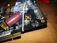
I.e., did you remove the two stock SMD caps (in the pic. below, you can see them below the stock X1 crystal, on either side of the SMD resistor--the caps are white)?
In almost every aftermarket tutorial I've seen, those caps are removed. Reason: the orig. (stock) is a crystal that needs external bypassing/filtering; whilst aftermarket is an oscillator (Vanguard) or clock (Burson, Audio-gd, TentLabs, etc.), and these have their own "built-in" caps.
Corvus5:
How exactly do you have your XO connected to the decoder?
I.e., did you remove the two stock SMD caps (in the pic. below, you can see them below the stock X1 crystal, on either side of the SMD resistor--the caps are white)?
An externally hosted image should be here but it was not working when we last tested it.
In almost every aftermarket tutorial I've seen, those caps are removed. Reason: the orig. (stock) is a crystal that needs external bypassing/filtering; whilst aftermarket is an oscillator (Vanguard) or clock (Burson, Audio-gd, TentLabs, etc.), and these have their own "built-in" caps.
Yes, I've done the battery trick before on an separate D/A processor (Musical Fidelity) -- and it did make a slight improvement. A diff. approach: the Less-Loss D/A uses batt. pwr in the analog section.
I think this PS "strategy" risky in a PC card due to my aforementioned criticism. But others guinea-pigging this mod is ok. Lesson will be learned EITHER way. Hope your PC stays safe in the long run, Coris.
I think this PS "strategy" risky in a PC card due to my aforementioned criticism. But others guinea-pigging this mod is ok. Lesson will be learned EITHER way. Hope your PC stays safe in the long run, Coris.
"Just fine"?My PC it were and is always safe and it run just fine, with a top notch modded Xonar inside, and an ultra high fidelity outputted sound...
So I guess your line IN problem from earlier is fixed?
Maybe it happen something with the IN stage of the board in those mod processes. I do not care about this aspect as I do not use that option anymore.
The Line IN problem in my sound card it have nothing to do with the PC as system. I never used Line In stage, I did not even known that is not working, I do not need it, and I don't care about that.
The mods on the board refer to the DAC stage and the analogue stage of the board, and this stage function just wonderful. My recording system is based on digital processing, and it use something else (inputs) than the analogue input or SPDIF on the sound card.
BTW, I could not see at least one picture of an your functioning mod on this board or another device?
Last edited:
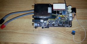
I tried to take a picture but it's hard to see. The old quartz was removed along with the pads. Clock V input gets the 5V, ground from the eeprom ground, output to the XTALI of the CMI before the capacitor. Placing it after the capacitor made the sound worse.
I already tried different ground, took the 5V from the on board 7805. Right now I use my own 7805 only for the clock with dedicated filtering with only capacitors. The input voltage for the 7805 comes from the onboard 7812 output.
The clock output goes to the CMI XTALI, the CMI sends it to the CS2000, then the CS2000 sends new clock to the PCM1792 (and probably ADC if dedicated). It's really hard to the take the picture, but I may it another aproach. Connections are not visible, some are hidden behind the non trasparent glue.
XO mounting
Corvus5: I can't see anything in your photos, but it's hard to macro-photograph ANYWAY with all those parts in the way, so why bother?!
Look again at #264 or here again ...
...and use those red number labels (with circles) as points of reference for this discussion.
Note there are two SMD ceramic caps (and an SMD resistor), immediately below stock X1, that are part of the X1-to-AV100 Xin ckt. I think Coris directly connected his XO's out pin to the AV100's X_in pin (via aforementioned pin lifting).
For the modder that posted the photo in #264 (head-fi.org), he connected the Vanguard TCXO's Out pin to POINT 1, and TCXO's Gnd to POINT 3. The TCXO's power (in) pin goes to +5v source via reg. of your choice.
WRT my query about the SMD ceramic caps (in Photo above, they are immediately below and parallel to X1 with an smd R in between)...here's what i mean about their removal ...
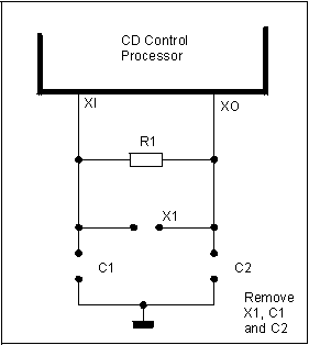
For an old aftermkt XO, the orig partsconnexion.com mounting instr. page no longer exists, but Archive.org has a record. Here are some schematics from that old page...
The typical circuit before XO installation:

Remove the crystal and two (?) capacitors.

Corvus5: I can't see anything in your photos, but it's hard to macro-photograph ANYWAY with all those parts in the way, so why bother?!
Look again at #264 or here again ...
An externally hosted image should be here but it was not working when we last tested it.
...and use those red number labels (with circles) as points of reference for this discussion.
Note there are two SMD ceramic caps (and an SMD resistor), immediately below stock X1, that are part of the X1-to-AV100 Xin ckt. I think Coris directly connected his XO's out pin to the AV100's X_in pin (via aforementioned pin lifting).
For the modder that posted the photo in #264 (head-fi.org), he connected the Vanguard TCXO's Out pin to POINT 1, and TCXO's Gnd to POINT 3. The TCXO's power (in) pin goes to +5v source via reg. of your choice.
WRT my query about the SMD ceramic caps (in Photo above, they are immediately below and parallel to X1 with an smd R in between)...here's what i mean about their removal ...
For an old aftermkt XO, the orig partsconnexion.com mounting instr. page no longer exists, but Archive.org has a record. Here are some schematics from that old page...
The typical circuit before XO installation:
Remove the crystal and two (?) capacitors.
One have to remove all the original clock components, including the quartz itself, before apply this mod with a new/better oscillator in place.
There is not very easy to remove that components. That because I chosen another way: lift it up the clock pin of the processor. This were for me a more easy task, than remove the old components. Even the old quartz it may rest in place. Using a needle and carefulness that pin it can be desolder and lifted a little bit up to not have contact with the pad. One may bend that pin (lifting it up) only one time at the desired level, and do not touch it after this operation is done. The clock pin it may be solder to the new oscillator as a last operation, after the new oscillator is very stable in it place (the rest of its pins are already soldered accordingly). One may use a little bit of very thin wire to connect the pin of the new oscillator (the out pin can be bendet to horizontal position to be more accessible to soldering operation) to the clock pin of the processor. Solder first the wire to the oscillator pin (out) and then at last to the lifted up clock pin of the processor. Do not solder the clock pin and the output pin of the oscillator all together. Use a thinner very short wire to connect those in between. Use very low power soldering iron to solder the clock pin and the oscillator output pin. Touch very carefully and solder the processor pin. One may avoid to mechanically stress that processor clock pin. It can be broken at once and then all the board can be just garbage...
This way should be very easy... It were for me at last.
After a "cleaning" operation in the thread (from moderators), I can see that all may previous attachments and pictures it were disappeared... This is quite bad
Last edited:
I found out why it were not functioning my Line IN. I have connected wrong the potentiometer in between... So, it were not something wrong with the card...
Is working now, but I can not get better than 21dB. So, it still not enough level to properly to make measurements. The case is under "treatment"
Is working now, but I can not get better than 21dB. So, it still not enough level to properly to make measurements. The case is under "treatment"
Attachments
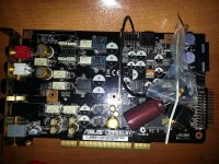
My Xonar ST
I just rec'd the Vanguard and plan to install it once I design an optimal XO ckt.
You do raise a valid point about wanting to know more info about others' systems/gear. Unfortunately, unlike some other tech forums, diyaudio does not provide enough characters space or a "Gear/Equip" category on one's Profile page. If they did, I would populate it with info and images.
Why pictures? What does that prove? See some posted details from earlier in this thread. I simply have a stock Xonar ST with changed opamps and LO output caps bypassed. I don't use it's HO.BTW, I could not see at least one picture of an your functioning mod on this board or another device?
I just rec'd the Vanguard and plan to install it once I design an optimal XO ckt.
You do raise a valid point about wanting to know more info about others' systems/gear. Unfortunately, unlike some other tech forums, diyaudio does not provide enough characters space or a "Gear/Equip" category on one's Profile page. If they did, I would populate it with info and images.
Removing xtal's small pF caps
Tent Labs XO mounting manual (page 4) instructs installer (of aftermarket Tent XO clock) to remove the pF caps around orig. crystal XO.
Tent Labs XO mounting manual (page 4) instructs installer (of aftermarket Tent XO clock) to remove the pF caps around orig. crystal XO.
Coris, take a look.
Yes, I see... How it have to look... Do you have to adjust the Balance to have the signals quite equal on the channels, or it just happen to be already balanced signal on your channels? It looks fine so far.
I do not know yet why I can not get more signal level. On the outputs I can have approx 25Vpp audio signal on max level. I suspect the input stage is not quite all right... I have used the sound "card" on the motherboard and it works better together with my STX, but is not just right to measure like this (different clock and different qualities...). I will see and find a solution for measurements...
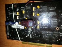
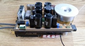
I can say that now is really finish to mod my board. There is not so much place for further mods on it...
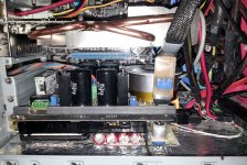
The final pictures here. The measurements will come another time...
Attachments
Last edited:
Fine-tune tips
Anyway ...
Try adding another reg. between the 7812 and 7805, such as 7808 (along with datasheet caps and Rs, etc.).
And try to solder out (i.e., remove) those two crystal SMD caps shown in the photo.
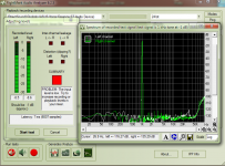
Did you post those graphs?I powered up the TCXO from the 7805. Not the low noise but still may be better than sharing the 5V of the DAC. I used the +12V from the xonar 7812. The noise, the THD, the IMD has rally changed. Doesn't look good. The fine tuned 5V is now detuned.
Anyway ...
Try adding another reg. between the 7812 and 7805, such as 7808 (along with datasheet caps and Rs, etc.).
And try to solder out (i.e., remove) those two crystal SMD caps shown in the photo.
The quality is too good. I'm upgrading my headphones as it is hard to notice any big difference from upgrading the xonar card.
The caps are floting in the space - the ground was destroyed along with the quartz pads. They are not being used and the clock is soldered betweend XTALI and its cap. The resistor is however stil present. Changing clock placement is something I don't want to do.
The caps are floting in the space - the ground was destroyed along with the quartz pads. They are not being used and the clock is soldered betweend XTALI and its cap. The resistor is however stil present. Changing clock placement is something I don't want to do.
- Home
- Source & Line
- PC Based
- Xonar ST/STX mods...