@Dario, in Google Doc's with the picture of the board and the drawn on schematic your circuit is incorrect for the 7912. You have it drawn with supply on pin 1, ground on pin 2, and regulated output on pin 3. The correct routing is ground on pin 1, supply on pin 2, and output on pin 3.
Correct.
Thanks for pointing it out, I've just updloaded an update pic.
")
All DAC chips are affected by jitter. But, you will never notice it - until you hear a better source, with lower jitter, and then you will know what jitter sounds like.
Playing an LP would be the best way to completely eliminate jitter, but achieving SPDIF lock will be an issue.
If you use a PC for playback, use good playback software such as cPlay + CMP or Vortexbox.
Playing an LP would be the best way to completely eliminate jitter, but achieving SPDIF lock will be an issue.
If you use a PC for playback, use good playback software such as cPlay + CMP or Vortexbox.
I've wasted 19 days for a no show from Jab Electronics for stand-offs/nuts and bolts- an email to find out what the delay was resulted in a Paypal re-imbursement - no explanation, no apology - avoid like the plague.
So can anyone point me to a site where I can buy 20-25mm stand-offs plus nuts and bolts - I need these as I intend to build the DAC using both sides of the PCB and it will be used virtically - air flow/convection current.
So can anyone point me to a site where I can buy 20-25mm stand-offs plus nuts and bolts - I need these as I intend to build the DAC using both sides of the PCB and it will be used virtically - air flow/convection current.
hey,
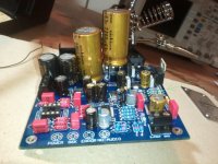
nearly done with this mini2496. i followed the BOM almost exactly, except i substituted some ceramics for the PLL, and some muse for the silmics. still waiting on some replacement 1.5uh inductors (1025-24K API Delevan [MIL] | 1134-1064-1-MIL | DigiKey) for L1 / L2 since the ones i bought were too big. they are rated at 560ma; should this be ok?
aside from being ocd about a few joints that i thought didnt flow properly, and unnecessarily desoldering and replacing, only to realize the groundplane was to blame and have it happen again, its gone well.
this pic shows how tight a fit the 2200uF turned out to be. i was able to wedge them in by installing the one near the 7809 first. however, the leads still come out pretty crooked. should this matter? also its very close to, but not quite touching the 7812 heatsink.
i see that the bypass caps for the 2200uF are omitted. would it be beneficial to use some spare 1000pF wima 100v for this role? or are they best left vacant?
also, i measured the 47k resistors before, and i thought they all measured OK. however i measured again after installing them and one of them is closer to 32k. i'm hoping this is due to it being paralleled with another resistance somewhere, but maybe it is bad? i've marked the area in the pic.
and one more question: the wima caps in the LPF are touching the solder joints of the resistors. i'm guessing its as good an insulator as the fiberglass PCB, but thought i'd ask if its ok anyhow.
thanks for the help and suggestions all.
-matt
nearly done with this mini2496. i followed the BOM almost exactly, except i substituted some ceramics for the PLL, and some muse for the silmics. still waiting on some replacement 1.5uh inductors (1025-24K API Delevan [MIL] | 1134-1064-1-MIL | DigiKey) for L1 / L2 since the ones i bought were too big. they are rated at 560ma; should this be ok?
aside from being ocd about a few joints that i thought didnt flow properly, and unnecessarily desoldering and replacing, only to realize the groundplane was to blame and have it happen again
, its gone well.this pic shows how tight a fit the 2200uF turned out to be. i was able to wedge them in by installing the one near the 7809 first. however, the leads still come out pretty crooked. should this matter? also its very close to, but not quite touching the 7812 heatsink.
i see that the bypass caps for the 2200uF are omitted. would it be beneficial to use some spare 1000pF wima 100v for this role? or are they best left vacant?
also, i measured the 47k resistors before, and i thought they all measured OK. however i measured again after installing them and one of them is closer to 32k. i'm hoping this is due to it being paralleled with another resistance somewhere, but maybe it is bad? i've marked the area in the pic.
and one more question: the wima caps in the LPF are touching the solder joints of the resistors. i'm guessing its as good an insulator as the fiberglass PCB, but thought i'd ask if its ok anyhow.
thanks for the help and suggestions all.
-matt
Attachments
bcmbob,
I live a good 135K from the nearest city - that's an expensive day long journey there and back. Luckily Hong Kong comes to the rescue again - great prices and normally quick delivery - going for both nylon and brass spacers.
Erin/Dario - I bought some special Russian spacecraft caps - 2% 1uf/250v polystyrene for coupling caps in my hybrid power amp - not as good as the de Graaf silver foil but close, loosing out on bass but very very good on voice, especially female, great stage depth, very impressed, overall a different, sound with some of it very life like and has convinced me more than ever to try some polystyrenes in this DAC. Unfortunately part of my ill-fated buy from Jabdog were a bunch of polystyrenes - will keep looking.
hey,
well the capacitors do fit, i found that a bit of pressure is necessary to keep them vertical while soldering. it sounds good, better than my modded fiio d3. using an opa2107 for now, i will try some opa827 soon.
i initially used a standard 100ma fuse, but it blew instantly. swapped it out for a 100ma time lag and its been working fine since.
now, to find a chassis. been eyeing the lmg heeger OH series, since its cheap and vented, but open to other suggestions. even the largest option would be a tight fit.
-matt
Attachments
sorry to trouble you clave, i'm trying to this without asking you too many questions and also not pester my dad too much...
but, to the right of C28 is a capacitor that is unmarked according to your paths and numbering diagram. what goes there?
pretty sure its the 1uf 50v
-matt
yep, it says 1u at that point, so that would make sense. but does this mean just use the stock one, or should i have ordered it? i can't see it on the BOM
i know i seem to have answered my own question because it's not on the BOM, but i just want to make sure...
oh, and thanks for the prompt reply!!
i know i seem to have answered my own question because it's not on the BOM, but i just want to make sure...
oh, and thanks for the prompt reply!!
Last edited:
yep, it says 1u at that point, so that would make sense. but does this mean just use the stock one, or should i have ordered it? i can't see it on the BOM
Use the stock one, that cap decouples the chip driving the leds... not in signal path.
i'm quite nervous about soldering the brown dog together (this is my first soldering project!). i have some very thin solder and a fine tipped iron. do you think the direct approach is ok, or is there some more reliable technique. i've seen clave mention tacky flux, but it expensive for a tube. being my first project, i'm quite cumbersome when it comes to soldering. any advice is much appreciated
There is nothing to be afraid of, just make sure you clean with alcohol the small browndog pcb. Solder just one terminal of opamp and check if the other pins are alligned and solder one by one. Make sure you have enough light and if you feel the need use a magnifying lens. If, by mistake, some pins are bridged use solder wick to take out the unneeded solder.
Good luck !
Good luck !
Blowing fuses
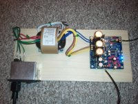
Hi all, finished assembling mine this morning using Dario's BOM - thanks so much for putting it together Dario!
Only problem so far is it's blowing the IEC socket's fuse at power-on about 50% of the time, and I'm already up to a 250mA (fast blow) which is quite a bit higher than the 100mA or so I've found mentioned in a few posts in this thread. What's everyone else using?
I have a 230V RN-20 R-core transformer btw - pretty standard there.
Thanks!
Bob, I am using 1 amp slow blow fuses. The problem is the transformer initially pulls a high current to form the magnetic field and charge the capacitors. Then it settles down to a lower current draw.
P.s. my transformer is 120VA with 4 sets of 15v-0-15v 30w secondary's, so 250ma fuse should work in slow blow form...
P.s. my transformer is 120VA with 4 sets of 15v-0-15v 30w secondary's, so 250ma fuse should work in slow blow form...
- Home
- Source & Line
- Digital Line Level
- DAC 2496 (AK4393) DAC KIT With CS8416+AK4393+5532