Thanks for the nice words. I used these resistors because I had them.I'm planning on using Fairchilds FQA19N20 and FQA12P20's however I also ordered some Toshiba 2SK1530
and 2SJ201's. For the bias I am going to see how high I can get it. First time building a solid-state amp so I am new to this. I'll check for cold solder joints as some don't look so good I can see more from the picture then with my reading glasses.
and 2SJ201's. For the bias I am going to see how high I can get it. First time building a solid-state amp so I am new to this. I'll check for cold solder joints as some don't look so good I can see more from the picture then with my reading glasses.
We are providing an update on some additional measurements that we have made.
Last night we rebiased the F5c V2.0 amplifier and took some measurements. One channel we perfectly biased at 376 mV across a MOSFET source resistor and an offset of -1 mv DC. The other channel had wandered a bit (about six weeks) with an offset of about 31 mV DC. After biasing again, both channels were at 375 to 376 mV across source resistors had about 1 mV DC offset and held quite stable.
Then, as requested, we took some measurements of the power supply while under load (each MOSFET 0.8 A bias). On the scope both + and –VDC going to amp boards was quite smooth. But with increased sensitivity, we could detect about 42 mV AC on the DC output to the amplifier boards.
And then we took some voltage measurements. As noted in our documentation, we expected to see about 34 VDC and -34VDC on the rails, but found exactly 30 VDC. Thus, despite our design, our 34 VDC rails have become 30 VDC rails. And, therefore, the bases of our cascodes are getting about ½ of that voltage to their 450 ohm resistors (R29 and R30), though that seems to be plenty, in that we bias quite easily. In retrospect, we should have expected about 30 to 31 VDC on the rails if, as has been suggested by others, we simply multiplied the secondary AC voltage by about 1.3 or so (24 X 1.3 = 31.2).
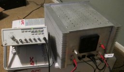
Next step was to measure the output impedance of our initial F5 (biased at 1.3 A) and of the F5c V2.0. Measurements and calculations were performed with a 1K Hz signal into the amp. The photo below shows the signal generator by our original F5. The F5 measured about .3 ohms while the F5c V2.0 measured 0.15 ohms. But these were rough measurements using a 5 and 10 ohm power resistor compared to an open circuit, and are only approximations.
With an identical 1 K Hz sine wave into the F5 and into the F5c V2.0, the F5c V2.0 (220 ohm feedback resistors to increase gain) put out just slightly double the voltage at the speakers compared to the F5. No surprise there.
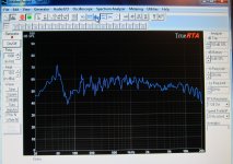
Frequency response measured in the room (microphone, software, etc.) were compared between the two amplifiers and were extremely similar. The speakers were Spendor S8Es (2 drivers each). (We did not take measurements of the isolated amplifiers, themselves, but plan to do so). We have shown a room measurement curve for the F5c V2.0, below. We have a bump about 50 Hz with a slight dip around 80, which we have seen in this room with other amplifiers, as well, making us believe it is the room, and to a lesser extent the speakers, more than anything else. With room measurements, both amps produced pretty much identical curves.
So, for those of you who have far more insight, the question of the day is the following:
if the amplifier biases easily (which it does), is there any reason to change the resistors in the voltage divider circuit that controls voltage to the bases of the cascode transistors Q101 and Q102 (BC550 and BC580) to get closer to ± 17 VDC?
Thanks
Steve
Last night we rebiased the F5c V2.0 amplifier and took some measurements. One channel we perfectly biased at 376 mV across a MOSFET source resistor and an offset of -1 mv DC. The other channel had wandered a bit (about six weeks) with an offset of about 31 mV DC. After biasing again, both channels were at 375 to 376 mV across source resistors had about 1 mV DC offset and held quite stable.
Then, as requested, we took some measurements of the power supply while under load (each MOSFET 0.8 A bias). On the scope both + and –VDC going to amp boards was quite smooth. But with increased sensitivity, we could detect about 42 mV AC on the DC output to the amplifier boards.
And then we took some voltage measurements. As noted in our documentation, we expected to see about 34 VDC and -34VDC on the rails, but found exactly 30 VDC. Thus, despite our design, our 34 VDC rails have become 30 VDC rails. And, therefore, the bases of our cascodes are getting about ½ of that voltage to their 450 ohm resistors (R29 and R30), though that seems to be plenty, in that we bias quite easily. In retrospect, we should have expected about 30 to 31 VDC on the rails if, as has been suggested by others, we simply multiplied the secondary AC voltage by about 1.3 or so (24 X 1.3 = 31.2).
Next step was to measure the output impedance of our initial F5 (biased at 1.3 A) and of the F5c V2.0. Measurements and calculations were performed with a 1K Hz signal into the amp. The photo below shows the signal generator by our original F5. The F5 measured about .3 ohms while the F5c V2.0 measured 0.15 ohms. But these were rough measurements using a 5 and 10 ohm power resistor compared to an open circuit, and are only approximations.
With an identical 1 K Hz sine wave into the F5 and into the F5c V2.0, the F5c V2.0 (220 ohm feedback resistors to increase gain) put out just slightly double the voltage at the speakers compared to the F5. No surprise there.
Frequency response measured in the room (microphone, software, etc.) were compared between the two amplifiers and were extremely similar. The speakers were Spendor S8Es (2 drivers each). (We did not take measurements of the isolated amplifiers, themselves, but plan to do so). We have shown a room measurement curve for the F5c V2.0, below. We have a bump about 50 Hz with a slight dip around 80, which we have seen in this room with other amplifiers, as well, making us believe it is the room, and to a lesser extent the speakers, more than anything else. With room measurements, both amps produced pretty much identical curves.
So, for those of you who have far more insight, the question of the day is the following:
if the amplifier biases easily (which it does), is there any reason to change the resistors in the voltage divider circuit that controls voltage to the bases of the cascode transistors Q101 and Q102 (BC550 and BC580) to get closer to ± 17 VDC?
Thanks
Steve
Attachments
I hadn't even noticed the boards were out of stock. How long have they been unavailable? I wanted to order a couple more sets.
cviller, thanks for the nice comments. Your help was essential to complete the project.
Steve
A few months anyways. I received a notification that they were back in stock but it was either an error or they were purchased as soon as they arrived.
Thankfully I'm not in a rush.
I have had my F5TV1 running for one day now all seems fine. I removed all current limiting including 550and 560.I have it running at .625 volt at source resistors.This is a very nice amplifier!I am about to make one for my friend and have two questions, maybe you can help:
1) Do cascode and current limiter transistors have to be matched?
2) Do I really need current limiting ZTX550/60? Nelson removed them from F5Tv1 which is almost F5cV2.
")
I am about to make one for my friend and have two questions, maybe you can help:
1) Do cascode and current limiter transistors have to be matched?
2) Do I really need current limiting ZTX550/60? Nelson removed them from F5Tv1 which is almost F5cV2.
1) no , and no
2) your choice - if you are going to play it safe , or you are safe
I am about to make one for my friend and have two questions, maybe you can help:
1) Do cascode and current limiter transistors have to be matched?
2) Do I really need current limiting ZTX550/60? Nelson removed them from F5Tv1 which is almost F5cV2.
Hi,
No, we didn't used matched cascode transistors.
Some claim the F5 and various versions sound better without the current protection circuit, though I haven't seen it demonstrated with, for example, frequency response curves, but also haven't looked in detail for them either. Personally, I don't want to take the risk. The circuit may save both your speakers and your MOSFETs.
2) Do I really need current limiting ZTX550/60? Nelson removed them from F5Tv1 which is almost F5cV2.
Leave the current limiting in. I am going through output fets like potato chips in my Turbo build. I still don't know what's happening, but it's doing a great job of killing the outputs.
Cascode Voltage
I'm not an expert but I'd think that a couple of volts here or there shouldn't make much difference as long as the FETs are not being stressed. It didn't seem to stand out as a critical point in the F-5T article.
If you consdier that without the cascode the drain of the upper input FET is closer to the rail (DC condition) and it that level changes considerably with the application of the cascode device; whether it changes from say 20V as in the non cascode version to say 1/3 of the rail voltage for the V3 and still gives excellent perfomance; the differences must be pretty small and subtle.
Matt
Soundchaser - thanks for the comment. BTW, might you have an opinion on the need to adjust the cascode voltage dividers given we have 30 VDC rails rather than 34? It doesn't seem necessary to me, given that the amp biases quite easily. Thanks.
I'm not an expert but I'd think that a couple of volts here or there shouldn't make much difference as long as the FETs are not being stressed. It didn't seem to stand out as a critical point in the F-5T article.
If you consdier that without the cascode the drain of the upper input FET is closer to the rail (DC condition) and it that level changes considerably with the application of the cascode device; whether it changes from say 20V as in the non cascode version to say 1/3 of the rail voltage for the V3 and still gives excellent perfomance; the differences must be pretty small and subtle.
Matt
- Status
- This old topic is closed. If you want to reopen this topic, contact a moderator using the "Report Post" button.
- Home
- Amplifiers
- Pass Labs
- F5c V2.0 Cascode Build Documentation