HV fet's will be around for quite some time.
Even just a few year's ago voltage voltage rating's above 1200V were are rare find.
Now voltages up to 2500V are a common place today and can be had for just a few dollars a pieces.
Remember that the voltages coming out of a step-up transformer just as dangerous as with any ESL type of system.
Typically a direct drive amplifier should employ some DC blocking capacitors as shown in the stax schematic as C33.
Regulation Is not necessary but is a good measure as good filtering will suffice as well.
Ripple voltage is a function of the value of the filter capacitor and the current drawn from the power supply and not its voltage output.
I can understand if one is not comfortable with working with such DC voltages.
In order to design a good cheap transformere that you can get down to 20Hz you need to select a rather large core as the number of primary turns is determined by the cross sectional area,Voltage input to the winding and its lowest frequency.
For instance the 100 watt toriod core that I am working with right now has 26 turns for the 6V winding and has a 1:40 transformation ratio with the two 115v winding that are already on it.
This makes about 500 turns for each HV winding and takes up the whole circumference of the core so there are two layer for both windings.
This increases its self capacitance and this particular one is not Bifilar wound as some are which makes it worse.
So to get to 20Hz at 6V input to the primary this core would require 3X the number of turns or about 78 turns (75 to 80) this also will also triple the number of turns for the HV windings to about 1500 turns each.
Because these turns will be bunched up together with little to no space in between each turn this will greatly increase the self capacitance of the transformer and thus increasing the extra load on the amplifier by have a lower impedance at the higher frequency's.
If you were to use a bigger core it would take much less primary turns to achieve your goal while keeping the HV turns down as well as having more room to not have the turns overlapping or touching each other and allow for a thicker insulation in between layer should you require it.
This helps to keep the transformers self capacitance at a low level and the resonate frequency above the audio band.
In the the first graph that esltransformer posted on his build states that it has 77pf of self capacitance.
http://www.diyaudio.com/forums/plan...p-up-measurements-part-1-2-a.html#post3347638
These are very good parameter's!!
After seeing the picture of it I can believe this as it is a fairly large C-core with lots of winding space to work with.
Form what I have read on a core this size it can handle about 880 watts at 50/60 hz.
And more exotic materials are very costly as well.
I don't know what is available in your area but over here we have a few company's that will supply cores and alphacore is one of my favorites and have very reasonable prices.
The also have C-cores and exotic materials as well,
Magnetic Cores - In Stock
something like a PN#130 for $31.50 might work well for your application if you don't mind winding it yourself.
Silicon Steel Toroidal Cores - In Stock
This core has volts per turn rating of .613 Volts per turn at 60Hz.
So for 6V at 60Hz this would mean only 10turns on the primary and 20 turns for 30HZ and finally 30 turns for 20Hz.
Multiply that by your ratio of say 40 and you have 800 and 1200 total secondary turns for 30Hz and 20Hz respectively.
Larger core core would be even better for less total turns!!
With 26ga. magnet wire you can get about 700 turns on one layer and with 30ga. you can get maybe 960 turns in one layer.
A C-core is much easier to work with but they do cost more.
There are company's that offer the HV winding already applied the trick is to have them wind it for a higher voltage than 230V and then add your own primary turns.
jer")
Even just a few year's ago voltage voltage rating's above 1200V were are rare find.
Now voltages up to 2500V are a common place today and can be had for just a few dollars a pieces.
Remember that the voltages coming out of a step-up transformer just as dangerous as with any ESL type of system.
Typically a direct drive amplifier should employ some DC blocking capacitors as shown in the stax schematic as C33.
Regulation Is not necessary but is a good measure as good filtering will suffice as well.
Ripple voltage is a function of the value of the filter capacitor and the current drawn from the power supply and not its voltage output.
I can understand if one is not comfortable with working with such DC voltages.
In order to design a good cheap transformere that you can get down to 20Hz you need to select a rather large core as the number of primary turns is determined by the cross sectional area,Voltage input to the winding and its lowest frequency.
For instance the 100 watt toriod core that I am working with right now has 26 turns for the 6V winding and has a 1:40 transformation ratio with the two 115v winding that are already on it.
This makes about 500 turns for each HV winding and takes up the whole circumference of the core so there are two layer for both windings.
This increases its self capacitance and this particular one is not Bifilar wound as some are which makes it worse.
So to get to 20Hz at 6V input to the primary this core would require 3X the number of turns or about 78 turns (75 to 80) this also will also triple the number of turns for the HV windings to about 1500 turns each.
Because these turns will be bunched up together with little to no space in between each turn this will greatly increase the self capacitance of the transformer and thus increasing the extra load on the amplifier by have a lower impedance at the higher frequency's.
If you were to use a bigger core it would take much less primary turns to achieve your goal while keeping the HV turns down as well as having more room to not have the turns overlapping or touching each other and allow for a thicker insulation in between layer should you require it.
This helps to keep the transformers self capacitance at a low level and the resonate frequency above the audio band.
In the the first graph that esltransformer posted on his build states that it has 77pf of self capacitance.
http://www.diyaudio.com/forums/plan...p-up-measurements-part-1-2-a.html#post3347638
These are very good parameter's!!
After seeing the picture of it I can believe this as it is a fairly large C-core with lots of winding space to work with.
Form what I have read on a core this size it can handle about 880 watts at 50/60 hz.
And more exotic materials are very costly as well.
I don't know what is available in your area but over here we have a few company's that will supply cores and alphacore is one of my favorites and have very reasonable prices.
The also have C-cores and exotic materials as well,
Magnetic Cores - In Stock
something like a PN#130 for $31.50 might work well for your application if you don't mind winding it yourself.
Silicon Steel Toroidal Cores - In Stock
This core has volts per turn rating of .613 Volts per turn at 60Hz.
So for 6V at 60Hz this would mean only 10turns on the primary and 20 turns for 30HZ and finally 30 turns for 20Hz.
Multiply that by your ratio of say 40 and you have 800 and 1200 total secondary turns for 30Hz and 20Hz respectively.
Larger core core would be even better for less total turns!!
With 26ga. magnet wire you can get about 700 turns on one layer and with 30ga. you can get maybe 960 turns in one layer.
A C-core is much easier to work with but they do cost more.
There are company's that offer the HV winding already applied the trick is to have them wind it for a higher voltage than 230V and then add your own primary turns.
jer
Last edited:
Yes, I have used stacked cores and it worked great except for the added capacitance takes a toll on the amplifier as shown in the post after this one,
http://www.diyaudio.com/forums/planars-exotics/161485-step-up-transformer-design-3.html#post2133105
However it works in a pinch and I did enjoy listening to my panel full range at a fair level.
I used to hold the panel next to my ear just like if it was a headphone driver and it just sounded incredible.
Although I did have a much higher D/S spacing so the bass went really low and clean!!!
Except (in my case) for the diaphragm resonance in which I had to filter this range out a bit.
But when I did I could believe what I was hearing!!!
jer
Last edited:
Toroid wise it can be done the way shown. Primary on top with required spacing and isolation barrier. Secondaries on each toroid in series. This way you have rather "small" voltage on each secondary. Self capacitance of the secondaries is of lesser importance due to "sectioning".
Attachments
HV fet's will be around for quite some time.
Even just a few year's ago voltage voltage rating's above 1200V were are rare find.
Now voltages up to 2500V are a common place today and can be had for just a few dollars a pieces.
Remember that the voltages coming out of a step-up transformer just as dangerous as with any ESL type of system.
Typically a direct drive amplifier should employ some DC blocking capacitors as shown in the stax schematic as C33.
Regulation Is not necessary but is a good measure as good filtering will suffice as well.
Ripple voltage is a function of the value of the filter capacitor and the current drawn from the power supply and not its voltage output.
I can understand if one is not comfortable with working with such DC voltages.
In order to design a good cheap transformere that you can get down to 20Hz you need to select a rather large core as the number of primary turns is determined by the cross sectional area,Voltage input to the winding and its lowest frequency.
For instance the 100 watt toriod core that I am working with right now has 26 turns for the 6V winding and has a 1:40 transformation ratio with the two 115v winding that are already on it.
This makes about 500 turns for each HV winding and takes up the whole circumference of the core so there are two layer for both windings.
This increases its self capacitance and this particular one is not Bifilar wound as some are which makes it worse.
So to get to 20Hz at 6V input to the primary this core would require 3X the number of turns or about 78 turns (75 to 80) this also will also triple the number of turns for the HV windings to about 1500 turns each.
Because these turns will be bunched up together with little to no space in between each turn this will greatly increase the self capacitance of the transformer and thus increasing the extra load on the amplifier by have a lower impedance at the higher frequency's.
If you were to use a bigger core it would take much less primary turns to achieve your goal while keeping the HV turns down as well as having more room to not have the turns overlapping or touching each other and allow for a thicker insulation in between layer should you require it.
This helps to keep the transformers self capacitance at a low level and the resonate frequency above the audio band.
In the the first graph that esltransformer posted on his build states that it has 77pf of self capacitance.
http://www.diyaudio.com/forums/plan...p-up-measurements-part-1-2-a.html#post3347638
These are very good parameter's!!
After seeing the picture of it I can believe this as it is a fairly large C-core with lots of winding space to work with.
Form what I have read on a core this size it can handle about 880 watts at 50/60 hz.
And more exotic materials are very costly as well.
I don't know what is available in your area but over here we have a few company's that will supply cores and alphacore is one of my favorites and have very reasonable prices.
The also have C-cores and exotic materials as well,
Magnetic Cores - In Stock
something like a PN#130 for $31.50 might work well for your application if you don't mind winding it yourself.
Silicon Steel Toroidal Cores - In Stock
This core has volts per turn rating of .613 Volts per turn at 60Hz.
So for 6V at 60Hz this would mean only 10turns on the primary and 20 turns for 30HZ and finally 30 turns for 20Hz.
Multiply that by your ratio of say 40 and you have 800 and 1200 total secondary turns for 30Hz and 20Hz respectively.
Larger core core would be even better for less total turns!!
With 26ga. magnet wire you can get about 700 turns on one layer and with 30ga. you can get maybe 960 turns in one layer.
A C-core is much easier to work with but they do cost more.
There are company's that offer the HV winding already applied the trick is to have them wind it for a higher voltage than 230V and then add your own primary turns.
jer
Thx. This esl transformer i made for my own home made esl. It's not made for a headphone.
The core that was used is a c-core type SU90B a 600w core, core material is HiB (M0).
Dear all,
More interesting posts, thanks
I have been giving direct drive more consideration but not yet, maybe in a month or so.
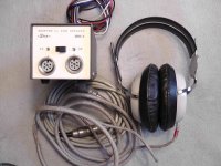
I have now wired up the 4 transformers but have yet to attach it to headphones, as I will wait until the plugs come in the post due Tueday.
I picked up a cheap STAX SRD-4 which is an designed for electret headphones, so I think it does not include the HV bias of a normal or pro stax headphones. This is not an issue as I have successfully built HV bias supplies on breadboard for the torroidal step up transformer circuit. Good news though is it does have a genuine 5 pin pro socket
The SRD-4 also contains a pair of transformer for stepping up the output of and amplifier, (1:50 from what I have read) and these are common on ebay at cheap prices. I will make a small box, to put under the SRD-4 and drill a socket in the bottom or side to pass the HV in.
This seems a cheap solution to the transformer solution and is a LOT smaller than 8 X 30 VA torroidal transformers. I will let you all know how they compare later.
Developments on the SR-3 and SRD-5:
I have mostly been listening to this system (late at night) while I built the supplies.
The SRD-5 started to hmm a lot, after a few hours listing, (rather than a little as before), I guess the capacitors are showing their age worse than I am, but they are older. So I took out the transformers, noting that Stax had been cheap and no terminal connectors on the transformers which is saving them a little money but not making fixing easy as fragile primary and secondary winding can easily be broken. To solve this I hot glued a 2 and a 3 way PCB terminal block to the top of the transformer and replaced the capacitors which I could now access without the transformer blocking access.
Sadly my stocks did not have 1uF 190 V capacitors so it only got 0.1 uF on the HV bias, this means that it wont blow up but sadly does mean that the main hum is still with me for now, at about the same level when pluged in so I guess the original electrolytic had about 1/10 of their value. ( ifdidnt
I cant help thinking the AKG's have better, cheaper and most importantly more comfortable ear pads than with either of these Stax headphones. I do suspect I might end up building some electrostatic headphones before the year is out designed to use AKG ear pads (easy to get as spares for a reasonable price).
More interesting posts, thanks
I have been giving direct drive more consideration but not yet, maybe in a month or so.
I have now wired up the 4 transformers but have yet to attach it to headphones, as I will wait until the plugs come in the post due Tueday.
I picked up a cheap STAX SRD-4 which is an designed for electret headphones, so I think it does not include the HV bias of a normal or pro stax headphones. This is not an issue as I have successfully built HV bias supplies on breadboard for the torroidal step up transformer circuit. Good news though is it does have a genuine 5 pin pro socket
The SRD-4 also contains a pair of transformer for stepping up the output of and amplifier, (1:50 from what I have read) and these are common on ebay at cheap prices. I will make a small box, to put under the SRD-4 and drill a socket in the bottom or side to pass the HV in.
This seems a cheap solution to the transformer solution and is a LOT smaller than 8 X 30 VA torroidal transformers. I will let you all know how they compare later.
Developments on the SR-3 and SRD-5:
I have mostly been listening to this system (late at night) while I built the supplies.
The SRD-5 started to hmm a lot, after a few hours listing, (rather than a little as before), I guess the capacitors are showing their age worse than I am, but they are older. So I took out the transformers, noting that Stax had been cheap and no terminal connectors on the transformers which is saving them a little money but not making fixing easy as fragile primary and secondary winding can easily be broken. To solve this I hot glued a 2 and a 3 way PCB terminal block to the top of the transformer and replaced the capacitors which I could now access without the transformer blocking access.
Sadly my stocks did not have 1uF 190 V capacitors so it only got 0.1 uF on the HV bias, this means that it wont blow up but sadly does mean that the main hum is still with me for now, at about the same level when pluged in so I guess the original electrolytic had about 1/10 of their value. ( ifdidnt
I cant help thinking the AKG's have better, cheaper and most importantly more comfortable ear pads than with either of these Stax headphones. I do suspect I might end up building some electrostatic headphones before the year is out designed to use AKG ear pads (easy to get as spares for a reasonable price).
Owen, maybe you could do some measurements about your transformers. Frequency respons?Dear all,
More interesting posts, thanks
I have been giving direct drive more consideration but not yet, maybe in a month or so.
I have now wired up the 4 transformers but have yet to attach it to headphones, as I will wait until the plugs come in the post due Tueday.
I picked up a cheap STAX SRD-4 which is an designed for electret headphones, so I think it does not include the HV bias of a normal or pro stax headphones. This is not an issue as I have successfully built HV bias supplies on breadboard for the torroidal step up transformer circuit. Good news though is it does have a genuine 5 pin pro socket
The SRD-4 also contains a pair of transformer for stepping up the output of and amplifier, (1:50 from what I have read) and these are common on ebay at cheap prices. I will make a small box, to put under the SRD-4 and drill a socket in the bottom or side to pass the HV in.
This seems a cheap solution to the transformer solution and is a LOT smaller than 8 X 30 VA torroidal transformers. I will let you all know how they compare later.
Developments on the SR-3 and SRD-5:
I have mostly been listening to this system (late at night) while I built the supplies.
The SRD-5 started to hmm a lot, after a few hours listing, (rather than a little as before), I guess the capacitors are showing their age worse than I am, but they are older. So I took out the transformers, noting that Stax had been cheap and no terminal connectors on the transformers which is saving them a little money but not making fixing easy as fragile primary and secondary winding can easily be broken. To solve this I hot glued a 2 and a 3 way PCB terminal block to the top of the transformer and replaced the capacitors which I could now access without the transformer blocking access.
Sadly my stocks did not have 1uF 190 V capacitors so it only got 0.1 uF on the HV bias, this means that it wont blow up but sadly does mean that the main hum is still with me for now, at about the same level when pluged in so I guess the original electrolytic had about 1/10 of their value. ( ifdidnt
I cant help thinking the AKG's have better, cheaper and most importantly more comfortable ear pads than with either of these Stax headphones. I do suspect I might end up building some electrostatic headphones before the year is out designed to use AKG ear pads (easy to get as spares for a reasonable price).
I think that will help much
Owen, maybe you could do some measurements about your transformers. Frequency respons?
I think that will help much
I think so too, how should I do this best?
My scope does not like > 300 V AC, and says things like it will die in it manual.
It looks like about 100 V is the maximum input that can be displayed.
My multimeter only 600 V AC.
I guess a potential divider into a ADC and optical the computer is the easiest?
Regards
Owen
Basically even integrated sound card should be enough.
You will have to make a resistor divider by yourself to drop voltage to <1V, lets say, 1000:1.
Optical decoupling is nice to have but is not absolutely necessary as long as you manage to avoid ground loops.
Lukas.
I describe how to do this in the links I posted in post 23.
http://www.diyaudio.com/forums/plan...ectrostatic-headphone-driver.html#post3367761
I have just recently posted some screen shots of some real tests as well.
Frequency response examples from are the HV output of the transformer as well as input and output voltage comparisons to the transformer.
There will be more stuff on this matter and a more detailed descriptions of how to make such measurements and what they mean.
I use both my scope and the computer to monitor the signals.
The transformer jig is working great and flawlessly so far.
I have been monitoring signals as high as 5Kv p-p into the computer and scope with no arcing or breakdown issues.
This is the very reason I started such a project, as is to show how to do such tests.
jer
You also need to find out what the maximum peak voltage is to your sound card and then design your voltage dividers around that value.
At first I though that 1v p-p as about what mine is, but, I later found out that 4Vp-p was the true maximum for my onboard sound system using the Realtek ALC 892.
I also have a GINA24 sound card it can handle an even higher voltage so I will have to adjust for this should I decide to start using it.
I have posted an update about this and I now employ some output buffers to minimize the loading errors on the voltage dividers and a 4X gain stage to account for my original error of voltage levels.
jer
I think so too, how should I do this best?
My scope does not like > 300 V AC, and says things like it will die in it manual.
It looks like about 100 V is the maximum input that can be displayed.
My multimeter only 600 V AC.
I guess a potential divider into a ADC and optical the computer is the easiest?
Regards
Owen
Owen,
If you want to measure your transformer(combination) you should use a 1:10 probe for your oscilloscoop. Not only you have 10 times less voltage on your scoop but also less capacitive load for the transformers. Next step is to add a 80pF capaciter and see what is happening (1:10 probe + 80pF = Stax headphone load)
Measure between 0 and + phase and later on between 0 and - phase ( there could be a differance between them)
Martin
Thankyou all on the measurement tips, little will happen tonight or tommorow as I am busy on other things, (that make money) but this said I will read and try all the things you guys said for measuement. I will get my self that ADC as I can see msyself making use of it more than once.
The load of stax headphones is very interesting information, that I was wondering how I could simulate as I have plans to do do tests and dont want to distroy the headphones.
Good ways to measure impedance would also be useful, esltransformer (Martin) I guess its just measure the current and voltage on the input and output of the transformer?
Regards
Owen
Indeed, A & V
I use a serie resistor of 10 Ohm and measure the voltage drop of this resistor and secondly the voltage drop of the transformer. I use always the same voltage drop of this serie resistor so I know that the transformer has always the same current.
All measurements I put in a spreadsheet and do some calculation on it and then make a graph.
If you use a (digital)voltmeter be sure that it is a true rms meter also for 20KHz!
Martin
Just a little post to keep things in one place.
Dear all,
My stax headphone sockets came in the post today
An interesting site showing some stax models and some schematics.
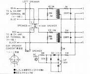
I have attached the schematic of the SRD-5 so it does not get lost.
Regards
Owen
Dear all,
My stax headphone sockets came in the post today
An interesting site showing some stax models and some schematics.
I have attached the schematic of the SRD-5 so it does not get lost.
Regards
Owen
Attachments
The SRD-5 and SR-3 that I got at a good price from ebay arrived today and I am pleasantly surprised how well they work in their original state. From what I have learnt already I can without doubt improve the SRD-5, and it should immediately have its capacitors replaced as although they don't do much work, and will have little effect on the sound, but they are older than me and could blow at any time.
The capacitors arrived today by post for the SRD-5, and other components for the potential divider, (so measurement can start) and some resistors and capacitors to adjust my Lambda drivers.
So I set up my Quad 303.
I have just been listening to :
Tchamantché by Rokia Traoré
Stairway To Heaven by Rodrigo Y Gabriela
Malka Moma Dvori Mete by Chet Nuneta
and I am very pleased.
The hum is gone and the sound is exceptionally good, bettering all my experiments so far. Subjectively it is better than the too bright high notes I had with my previous experiments.
Its getting close to optimization time and being critical, rather than just being happy it sounds good.
So lets start with what I don't like:
(a) In the circuit in the SRD-5 the bias that charges the electrostatics is driven direct from the mains in an asymmetric way, with no decoupling transformer, so plugged in one way it generates hum, and one way not (German plugs can be plugged in swapping live and neutral, something I have found most hifi/musical people dislike but most consumers have no problem with) I will at least partially solve this my moving the plug to the IEC type.
(b) The SRD-5 plugs are not Stax plugs but have been replaced with high quality 240 degree din plugs with screw plugs. (now its confirmed they are screw locked Din plugs as I found a 240 Din plug in my stocks) I am unsure I can be bothered to change this in the short term as they don't look too dangerous and my Stax plug will be difficult to attach as safely to a cable.
(c) Their is some pickup from the cable. (did not notice it before as was too much hum)
(d) I suspect theirs still some supersonic oscillation that I can perceive but not hear, this needs to be confirmed by measurement, the capacitors responsible for this are very small ceramics that I have not yet replaced yet)
(e) The SRD-5 box is too small to put in another circuit board.
(f) The polyester capacitors I intended to use for the bias supply are just a little to big to fit in the gap between the PCB and the transformer. I had to use the backup electrolytic capacitors for the power supply. I am convinced I could make a better bias power supply, using transformer decoupling and a lot more filtering after the voltage multiplier, but on the good side it is surprising how slowly the volume decreases when you unplug the SRD-5 from the mains.
I am convinced that although I now feel the Stax SR-3 / SRD-5 is the best pair of headphones I have ever had, I am not yet confident the Bass is as good as it can be, judgement can wait though as the headphones are new and my opinion can wait till after I have built the measurement tools and received the new Analogue to digital converter.
The Stax Lambda (which I started this thread about) has a Stax plug so I have not connected it to the SRD-5, and I think that my experiments will focus on this soon but not quiet yet, I suspect I will wait until I start customizing the Stax electret driver which should arrive some time soon and adding a bias circuit. I am also seriously considering building a direct drive amplifier but measurements will happen first.
Regards
Owen
First i have to tell that the original Stax transformer in the SRD-7 has a 1:60 step-up. Mine has 1:50.
A esl transformer is a push-pull transformer so it has a + and - fase. In fig. 1 you see that the Stax transformer has not equal fase response for the high frequencies. This is one of the reasons i would like to have a better transformer. Secondly i would like to have a transformer with very low losses. Third i like a transformer-esl combination wich is easy to drive with any amplifier so impedance should be high even at 10Hz or 20kHz
I use for my headphone 500V polarisation. I not use a 1 Ohm resistor but a 0.47 Ohm, i just use a 1 Ohm for measurements. Adding a series resistor is not good for the low frequency response and also give more distortion.
The next stage of my tweaking the home made driver will start soon, thank you for giving me some advice on the resistance range.
The current circuit on the SRD-5 has 4 Ohm in series and 30 Ohms in parallel with the low tension in the transformer. But I guess their designs had to work with Amplifiers designed for 16 Ohms, and compromise on sound for universality and not breaking amplifiers?
The capacitor, in parallel with the headphone is not understood my me? Why is it like that? AM I right with my first guess that it was making the speakers have a low pass filter, the more I think about it this explanation it seems wrong, and since the headphones behave like a very non ideal capacitor why add more capacitance to the high tension?
Regards
Owen
- Status
- This old topic is closed. If you want to reopen this topic, contact a moderator using the "Report Post" button.
- Home
- Loudspeakers
- Planars & Exotics
- Making an electrostatic headphone driver.