TPC already really needs an enhanced VAS/TIS to show any big difference
even higher order compensation schemes really only benefit amps with even more gain stages - NDFL, "error correction" local loops - the PGP amp
and higher order schemes have added nonlinear clipping, slewrate limit triggered oscillation modes that require attention
even higher order compensation schemes really only benefit amps with even more gain stages - NDFL, "error correction" local loops - the PGP amp
and higher order schemes have added nonlinear clipping, slewrate limit triggered oscillation modes that require attention
The topology is surely well known in IC design, although I can't say which opamp used this first. The name is somewhat misleading, as this is not actually a current mirror. A current mirror has a current input (low Z) and a current output (high Z), and the currents are modulated by the signal. Here there are just two outputs--with common-mode feedback, but no differential signal modulation. Perhaps "active load with common-mode feedback" is more accurate.
Samuel
Samuel
The differential current mirror shown on p. 146 of the book seems a clever idea.
A quick Internet search did not turn up much, does any one have an analysis or references, or was it invented by Bob himself?
David
Hi Dave,
I first used it in my MOSFET Power Amplifier with Error Correction in 1983. I designed it myself, but that doesn't mean that someone else did not do the same thing or something similar before. If they did, I just was not aware of it.
The semantics of the term differential current mirror may be questoned, but I came up with the term as a derivative of what I consider to be the ordinary (single-ended) current mirror load that we are all familiar with in the input stages of power amplifiers, where it acts as a load for one side of the LTP and its output is connected to feed the net current to the input base of the VAS. This circuit does essentially the same thing, but differentially from both sides.
If it was used in op amps in the 70's or early 80's, you might be able to find it in a patent search, since such stuff was regularly patented back then. Even the Widlar current mirror was patented way back when, even though once one sees it, it looks pretty obvious. However, searching for it might require the use of numerous different semantics to find it.
Calling it something like a differential current source load with common mode feedback is certainly accurate as well.
Best,
Bob
One thing i do not agree with in Bob s book is that it is said that
"parralelling mosfets is not as straightforward as with BJTs".
Might be true for verticals but laterals can be parralelled even easier
than BJTs.
Indeed , the part devoted to laterals is somewhat symbolic ,
it would have been great to give thoses devices a little
more attention.
Perhaps in the next edition?.
Last edited:
... Perhaps "active load with common-mode feedback" is more accurate.
Even the Widlar current mirror was patented way back...once one sees it, it looks pretty obvious.
That's what makes a circuit brilliantly simple rather than just simple! I would be more proud of a circuit that looks obvious after you have seen it, but that nobody did see, than any other. I hope my current idea turns out like that.
However, searching for it might require the use of numerous different semantics to find it.
Calling it something like a differential current source load with common mode feedback is certainly accurate as well.
Both your and Samuel's phrases are helpful descriptions of different aspects so it is a pity that multiple different terms makes searches tedious. That was part of the reason I enquired here - in case there was another term I missed.
Thank you both for your replies. I will study the patents that Samuel referenced.
I have some questions on LTP to VAS connections that may also be in your respective areas, but I started a new thread for simplicity.
Best wishes
David
Last edited:
Hi Bob,
Reading your book, Santa gave it to me for xmas, this year, what a nice guy. Excellent book, wish I had a book as well written as this one, when I attended College, back in the late 70's.
P.S. Thx for the LTSPICE additions as well!!
Cheers
Rick
Hi Rick,
Thanks for those kind words.
Cheers,
Bob
One thing i do not agree with in Bob s book is that it is said that
"parralelling mosfets is not as straightforward as with BJTs".
Might be true for verticals but laterals can be parralelled even easier
than BJTs.
Indeed , the part devoted to laterals is somewhat symbolic ,
it would have been great to give thoses devices a little
more attention.
Perhaps in the next edition?.
Hi wahab,
The paralleling issue for MOSFETs is indeed an interesting one, and much of what you say is true. I think the main reason I said that it was more difficult was because of the relative ineffectiveness of source degeneration in sharing current among MOSFETs that are not matched. The gate threshold voltages of randomly-selected MOSFETs can vary quite a bit, resulting in current hogging in the absence of source resistors. It is true that this is a smaller problem with laterals because they have lower gm and they also have the somewhat self-regulating characteristic in which conduction decreases as they get hotter over much of their operating current range; so one device that is hogging gets hotter and tends to back away from its hogging. This is not the case for verticals in the current ranges where we normally operate them (the TC crossover occurs at a much higher current in verticals).
Nevertheless, even with laterals manufacturers generally must used matched sets of MOSFETs, be they vertical or lateral.
It is desirable to use matched sets of BJTs as well, where they are matched for beta, but this is not as critical a matter for bias stability for BJTs when they are used with a reasonable value of emitter resistor.
I'll try to give more attention to laterals in the next edition. I may even add a chapter or two on tube amplifiers. Many people were disappointed that I did not say anything about tubes, but instead went to the "dark side" in covering class D amplifiers
") .
.Cheers,
Bob
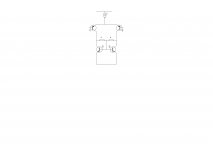
I have a few comments/questions about this topology.
This is a fully differential amplifier.
To accomplish this two equal loads are placed in the two collectors of the input differential amplifier, the ouput beeing take differentially.
To have enough gain, these two loads should have very high resistance.
In IC design this is done by putting two identical current sources one in each collector. But now we have a biasing problem the current source of the differentail amplifier and the two loading currents sources are both establishing the bias which is not possible.
The trick is to create a signal equal to the common mode and to feed it back to control one of the bias source, in this way there is only one bias controling element. One simple way to do this is to use two identical resistors as in the fig attached. The mid point of the two resistors cancels the differential signal and is proportional to the common mode voltage. This is applied to the bias voltage of the two current sources.
But now we have a voltage gain equal to gm ro R where ro is the output impedance of the loading current sources, the resistor should again be high. In IC technology the resistors are limited. A way to increase them is to insert an emitter follower before each resistors and this is the topology found in the book.
The question I have is : In discrete design we can use very high value resistors. Should we not have essentially the same performance by simply putting two equal and high resistors either as in the figure or simply in each collector.
JPV
Attachments
Found three copies at a Half Price Books in brand new condition.
I've previously lost two to possibly permanent loan-outs, So I
picked up a few spares. Wonder how long these will last me?
Isn't it a little too soon for this book to be found at discount?
Nineteen bucks I gave, couldn't believe it. Half? Not even half...
I didn't hesitate to quibble over which edition.
Last edited:
Hi Bob,
What's the prefered sensing location of a VBE device, for vertical mosfets (k1530 & j201 pair), if they are matched for 5% Vgs in a typical high power application, perhaps with a +/- 75v supply...? On top of the device or heatsink...? I 've read that mounting the Vbe on heat sink would suffice in chapter 11 (fig 11.8) of your book. Does mounting the device on top of the output devices would over compensate....?
What's the prefered sensing location of a VBE device, for vertical mosfets (k1530 & j201 pair), if they are matched for 5% Vgs in a typical high power application, perhaps with a +/- 75v supply...? On top of the device or heatsink...? I 've read that mounting the Vbe on heat sink would suffice in chapter 11 (fig 11.8) of your book. Does mounting the device on top of the output devices would over compensate....?
I'll try to give more attention to laterals in the next edition. I may even add a chapter or two on tube amplifiers. Many people were disappointed that I did not say anything about tubes, but instead went to the "dark side" in covering class D amplifiers
My personal preference is for more information on solid state, performance aspects. If practical limits on book size mean less or no Class-D and tubes then that is fine. There is always a balance between depth and breadth. In this case both topics are rather specialized and self-contained so they would be a minimal loss compared to the benefit of more space for the central focus of the book.
Best wishes
David
Last edited:
If practical limits on book size mean less or no Class-D and tubes then that is fine. … In this case both topics are rather specialized
Class-D is the future. More on Class-D! More on advanced high-order loops and how to make them stable under clipping conditions. Basically tell us all about NCore I'll try to give more attention to laterals in the next edition. I may even add a chapter or two on tube amplifiers. Many people were disappointed that I did not say anything about tubes, but instead went to the "dark side" in covering class D amplifiers
Cheers,
Bob
Definitely more attention to laterals. These days, the SS manufacturers are putting much more emphasis on switching type applications. Hopefully, more attention will make more devices useful for linear amplification more available. It's not good that this has been so thoroughly short changed lately. There are already more than enough sub standard SS amps on the market, and SS doesn't have to sound as horrible as it does all too often. However, sonic excellence still needs devices that can perform well in that application.
"I may even add a chapter or two on tube amplifiers".
Don't. Hollow state will require more than a "couple of chapters" to do it right. Many of the concepts carry over from SS to HS, but the design details are very different. Besides, Morgan Jones has this covered. Maybe more about Class D, for those who're interested?
"Class-D is the future".
Not really, it's been around for quite a few dog's ages now. You can also implement Class D in hollow state, as it was first done back in the early '50s.
- Home
- Amplifiers
- Solid State
- Bob Cordell's Power amplifier book