Your last point applies to nearly everything. There is nothing in the
standards to prevent silly levels of very low frequencies down to DC.
Got it, thanks.
Hi,
Your last point applies to nearly everything. There is nothing in the
standards to prevent silly levels of very low frequencies down to DC.
rgds, sreten.
Hi,
Just to add, AV systems rely on effective subsonic filtering of the sub
channel to its frequency limits, allowing encoding of very low frequencies
in the 0.1 channel, to be then properly managed by the AV system.
Music CD's are not AV, don't have that luxury, and consequently
do not have anything like the same v.l.f. content as AV in general.
rgds, sreten.
If you see your speaker cone moving around 20hz 10hz or less. you got a good subwoofer and amplifier..
I have a soundcard modified to be DC coupled, the small signal opamp output will drive a small 3" speaker with a 1hz sine tone, with movement I can feel with my fingers. There is certain audible output but does not produce a discernible tone. This is a case when audio efficiency is so low that the distortion dominates over any meaningful signal, you will see it, but not necessarily hear it, even if you had an adequate HIFI setup. You won't get anywhere close to actually producing a meaningful 1hz sound unless you have built your house as part of the speaker system.
it wouldn't have as much power would it though right? and wouldn't that introduce ultrasonic pulses into the audio signal instead of normally just using a capacitor to block DC?
Oh yikes I just tried putting 19 volts to the amplifier chip for a few seconds
And Omg the 10 watt speaker bottomed out from a 5 watt IC chip amplifier
And there was no amplifier distortion.... only the bottoming out of the 10 watt speaker
Yikes I just got over 10 watts out of a 5 watt amplifier chip O.O that's a little scary..
But I hooked it back up to the 12 volt power supply instead so I think the chip is okay... It didn't get warm when I unplugged the power cord and checked the chip..
Maybe the massive heatsink helped save the chip?
[Edit: Wrote this much earlier but walked away without hitting "Post Reply".]
I would also be worried about possibly killing the speaker, in that situation.
If everything still works, count yourself lucky. You might have degraded the performance of the chipamp, somewhat, or shortened its lifespan. But maybe not.
Your high-pass input filter is probably not restricting "ultrasonic pulses" from getting into the amp. I don't know why there would be any ultrasonic signal at your input. But there WILL be RF (Radio Frequency) junk, there. So you should, ideally, also use a low-pass filter, RIGHT before the input pin.
Unless you have a dual-polarity supply and the chip has both plus and minus input pins, you should be able to just insert a series resistor, very close to the input pin, and insert a capacitor to ground, connected between the resistor and the input pin.
You'll want the cutoff frequency of that low-pass RC filter to be around 350 kHz, or maybe lower. You could try a 1K series resistor, which would mean a capacitor to ground of 1 / (2π x 350000 x 1000) = 450 pF. You could try two 220 pF caps in parallel, for that, or use a 470 pF cap, or just drop it back to 330 pF, which would make the cutoff frequency 1 / (2π x .00000000033 x 1000) = 482 kHz. That's getting into the AM radio band so it might be a little too high. A 470 pF cap would make it 339 kHz, which should be fine. Or you could even go lower, with a slightly larger cap.
Switching gears somewhat:
If your power leads are longer than an inch or so, you should have some capacitance from RIGHT AT the power pin to ground. I would rcommend a 0.1 uF X7R ceramic cap in parallel with an electrolytic of at least 10 uF. I would also try 100 uF or 220 uF or more, there, to see if you can hear a difference.
I calculated that 7.9 uF wold be the minimum, at the power pin, if you wanted to be able to go from 0 Watts to 5 Watts (into 8 Ohms) in one microsecond, while disturbing the power supply voltage by no more than 0.1 Volt. But your amp might very well be able to do it faster than that, and its feedback loop might need to be able to respond to frequencies of up to a few hundred kHz. So larger might be better. Also, that figure doesn't account for your bass-driving needs. So the bass response might also benefit from a much larger capacitor between the power pin and ground, especially if your power wiring is very long, or there is much inductance anywhere upstream from the power pin.
You should also tightly twist together the signal and signal ground reference input wiring, ALL the way from end to end. And do the same for your positive and negative DC power wiring, and your speaker wiring. That will help keep RF and other interference out. Everything is an input, for RF. And it might cause subtle degradation of the chip's performance (or it might sometimes cause not-so-subtle problems).
Also, if you run a separate wire all the way back to the power source's ground or negative output, for the grounds that are from components that go to the input pin, it might help the sound quality significantly. i.e. Don't run them together with the speaker ground, or the ground for the caps at the power pin.
I calculated that 7.9 uF wold be the minimum, at the power pin, if you wanted to be able to go from 0 Watts to 5 Watts (into 8 Ohms) in one microsecond, while disturbing the power supply voltage by no more than 0.1 Volt. But your amp might very well be able to do it faster than that
I would be very interested to know how you performed that calculation, if you'd care to explain it.
Also, under what circumstances would an amp ever shift from zero volts to the rail voltage in one microsecond (assuming that is the case you're considering)? Wouldn't it take something like a 250kHz sine wave to do that?
EDIT: also, how exactly does a larger power supply capacitance improve bass response? To my knowledge all the capacitance does is decrease ripple voltage, for a given current. Is it just that heavy bass draws higher currents for longer (due to the longer lasting peaks of the waveform) and hence causes more ripple? And if the lowest points of the rippling rail voltage are low enough your maximum output power drops?
Last edited:
I noticed some duscussion about whether or not sub-1-Hz energy couold exist in a recording. I noticed some very low frequency activity in a song that I was using to test a DC servo circuit.
This was while I was using a WAV file of a portion of a song (less than one minute of music, if I recall correctly), as an input to an LT-Spice simulation of an amplifier with a DC Servo.
It was a bit of an eye-opener, for me, because I had always reasoned that every music signal's average would only stray from zero for as long as a half-cycle of the frequency of the lowest note that was played.
Apparently I was completely wrong about that. And it made my servo's output (before summing with the signal path) wander around, as it "corrected" the average to zero. (I think that I realized then that the servo's time-constant needed to be much longer.)
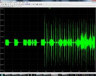
Anyway, attached is a screen image that I just made, from LT-Spice. It shows the amplifier's INPUT signal, from a WAV file containing the beginning of an AC/DC song called "Highway to Hell". I chose that song for the servo test precisely because it is very "bursty".
As can be seen from the time-domain plot in the attached image, the song starts with drum strikes only, for about 9.5 seconds, and then short electric guitar "chord-bursts" are added, until a little after 18 seconds, when vocals are added (if I am recalling it correctly, just from looking at the plots).
The DC offset appears to be near zero, judging by the level during the gaps between drum strikes. But there is significant asymmetry evident. For example, examine the plot between 10 and 12 seconds. This is the input voltage so assuming an amplifier gain of 20 there could easily be output excursions of more than 1.5 volts away from zero, during the passage shown in the plot, at rates of roughly 0.5 Hz.
There is also some tabulated dynamic DC offset data that I posted during the original servo simulation experimentation that was performed and reported here back in 2007, which can be seen at:
http://www.diyaudio.com/forums/chip-amps/107246-dc-servo-question-12.html#post1311148
That post at that link also includes a screen image with a much longer duration plot of the same song (60 seconds of it).
---
There is another possibility, though: It could be a form of "motorboating" that is causing the OP's speaker to deflect at a slow rate. I have not read all of the details of the OP's configuration from this thread, yet (my apologies). But, perhaps there are mismatched RC time-constants in the system. I can't remember the details of the mechanism, right now, but perhaps something like having a lower RC time-constant (faster response) for something upstream (e.g. input filter or feedback loop), compared to the RC time constant of something downstream (e.g. feedback loop or output filter), might cause a low-frequency instability. I believe that the response speed of subcircuits should never decrease too drastically, as the signal makes its way from input to output.
Cheers,
Tom
This was while I was using a WAV file of a portion of a song (less than one minute of music, if I recall correctly), as an input to an LT-Spice simulation of an amplifier with a DC Servo.
It was a bit of an eye-opener, for me, because I had always reasoned that every music signal's average would only stray from zero for as long as a half-cycle of the frequency of the lowest note that was played.
Apparently I was completely wrong about that. And it made my servo's output (before summing with the signal path) wander around, as it "corrected" the average to zero. (I think that I realized then that the servo's time-constant needed to be much longer.)
Anyway, attached is a screen image that I just made, from LT-Spice. It shows the amplifier's INPUT signal, from a WAV file containing the beginning of an AC/DC song called "Highway to Hell". I chose that song for the servo test precisely because it is very "bursty".
As can be seen from the time-domain plot in the attached image, the song starts with drum strikes only, for about 9.5 seconds, and then short electric guitar "chord-bursts" are added, until a little after 18 seconds, when vocals are added (if I am recalling it correctly, just from looking at the plots).
The DC offset appears to be near zero, judging by the level during the gaps between drum strikes. But there is significant asymmetry evident. For example, examine the plot between 10 and 12 seconds. This is the input voltage so assuming an amplifier gain of 20 there could easily be output excursions of more than 1.5 volts away from zero, during the passage shown in the plot, at rates of roughly 0.5 Hz.
There is also some tabulated dynamic DC offset data that I posted during the original servo simulation experimentation that was performed and reported here back in 2007, which can be seen at:
http://www.diyaudio.com/forums/chip-amps/107246-dc-servo-question-12.html#post1311148
That post at that link also includes a screen image with a much longer duration plot of the same song (60 seconds of it).
---
There is another possibility, though: It could be a form of "motorboating" that is causing the OP's speaker to deflect at a slow rate. I have not read all of the details of the OP's configuration from this thread, yet (my apologies). But, perhaps there are mismatched RC time-constants in the system. I can't remember the details of the mechanism, right now, but perhaps something like having a lower RC time-constant (faster response) for something upstream (e.g. input filter or feedback loop), compared to the RC time constant of something downstream (e.g. feedback loop or output filter), might cause a low-frequency instability. I believe that the response speed of subcircuits should never decrease too drastically, as the signal makes its way from input to output.
Cheers,
Tom
Attachments
I would be very interested to know how you performed that calculation, if you'd care to explain it.
Also, under what circumstances would an amp ever shift from zero volts to the rail voltage in one microsecond (assuming that is the case you're considering)? Wouldn't it take something like a 250kHz sine wave to do that?
EDIT: also, how exactly does a larger power supply capacitance improve bass response? To my knowledge all the capacitance does is decrease ripple voltage, for a given current. Is it just that heavy bass draws higher currents for longer (due to the longer lasting peaks of the waveform) and hence causes more ripple? And if the lowest points of the rippling rail voltage are low enough your maximum output power drops?
Hi Imaurits,
[I do not consider myself to be an expert. But I am slowly re-learning a lot of things.]
Sure. A while back, I was wondering how to choose the values for decoupling caps, and ended up opening a fairly-large but quite-appetizing "can of worms". <grin>
First, you have to understand that the signal that we hear, from an audio power amplifier, is, EXACTLY, the CURRENT from the power supply reservoir capacitors and the decoupling capacitors. Almost all of that current comes from either the PSU's reservoir caps or the power output devics' decoupling caps. (A small fraction comes directly from the rectifiers, but only when a charging pulse is occurring.)
The proof that makes that completely obvious is in an image that I posted:
http://www.diyaudio.com/forums/power-supplies/216409-power-supply-resevoir-size-38.html#post3117390
where you can see that the amplifier output signal is coming directly from the PSU reservoir caps (there are no decoupling caps in that example).
So that means that the power supply VOLTAGE is relatively uninteresting. After all, it's not even supposed to change! And the rectifier-induced ripple voltage is easy to make as small as we want, and is only important when an amp's PSRR (power supply rejection ratio) is poor, or craps out at higher frequencies, OR, if we ask too much of the supply and drag its voltage too low. The CURRENT is where the action is. [The _REAL_ "signal path", the one that we actually HEAR, is current that goes straight from the PSU and decoupling caps through the power output devices and directly to the speakers.]
Second, let me explain that while the terms "bypass capacitor" and "decoupling capacitor" are often used interchangeably, I look at them in one particular way, which might also motivate you to appreciate the importance of, especially, decoupling capacitors:
Bypass caps are usually small-size (and usually also small-value) caps that are placed and connected very near to the power supply input for an active device, in order to try to prevent high-frequency instability, because most transistor-based amplifiers have a hidden positive feedback path for high-frequencies, through the power rail. So the bypass capacitance is there to try to short-circuit any HF to ground, to prevent instability (e.g. oscillation).
Decoupling caps, which are much more interesting, to me, are placed at the power supply inputs for active devices so that when a device suddenly demands (or, actually, "allows") a fast change in its DC input current (i.e. a "transient"), that fast-changing current doesn't have to try to come through the self-inductance (and resistance) of the power rail conductors.
The decoupling cap acts as a small point-of-load power supply, with very low impedance because it's only millimeters away, which means that there isn't a lot of inductance or resistance due to the lengths of the power and ground conductors.
The decoupling cap accomplishes at least three very important tasks:
1) [Voltage Spikes:] If the fast transient currents had to come all the way from a more-distant capacitor, e.g. from the power supply reservoir caps, then a large voltage spike would be induced on the power and ground rail conductors, mainly because of their inductance, because, for an inductor, V = L di/dt, which points out that the voltage developed across the rail conductor's inductance is proportional to the time-rate-of-change of the current.
So the voltage spikes can be quite large, even if the current is tiny, as long as the current's amplitude is changing rapidly. The name "decoupling cap" comes from the fact that they are used, in part, to try to "decouple" a local subcircuit's or device's potential for creating power rail voltage disturbances from the rest of the power distribution system.
2) [Transient Distortions:] a) If the fast transient currents had to come all the way from a more-distant capacitor, e.g. from the power supply reservoir caps, then they would often not be rendered accurately-enough, as reflected in the devices output current or voltage.
The inductance of the power rail conductor will always cause a delay in the arrival of the current and a change in the shape of the arriving current's amplitude vs time waveform, because it will delay different frequency components by differing lengths of time.
When an analog signal is being reproduced by the power output stage of an audio amplifier, for example, trying to pull transient currents through too much conductor length results in transient distortion. The audio waveforms' rise-times are altered. Basically, the phase angles and amplitudes of the many Fourier frequency components, that are what gives the correct shape to anything more-complex than a single-tone sine wave, would all be altered in frequency-dependent ways.
That would be "a BAD thing". For something like a square wave, it would result in distortion of the rising and falling edges, and the appearance of what looks like ringing (decaying-amplitude oscillations) just after each edge. But, in general, it could alter or blur the timing of everything in the sound waveform, possibly harming the information that our brains use to perceive the soundstage image.
b) There is also an important "need for speed" because of the feedback loop that is usually used for amplifiers. The term "harmonic distortion" implies the existence of harmonics. The feedback system has to try to react to, and cancel, any harmonics, to prevent them from going through to the output and becoming part of a higher level of harmonic distortion. Harmonics are undesired multiples of some desired frequency. That means they are at higher frequencies. In a fast-responding active device, it is necessary for the feedback system to be able to deal with distortion signals that contain frequencies up to the limit of the device's ability to respond. Chipamps are usually very slow, compared to most discrete transistor circuits. But an LM3886 chipamp, for example, has a typical maximum slew rate spec of 19 Volts per microsecond! If we use Henry W. Ott's equation for the maximum frequency content in the rising edge of a pulse waveform, f = 1 / (Pi x trise), then a 1 microsecond edge is equivalent to 318.31 kHz. But if it can slew 19 Volts in 1 us, maybe it can slew 1 Volt in 1/19th of a us.
At any rate, in order to not leave a bottleneck that degrades a device's ability to perform at its rated specifications, we must use decoupling capacitors with low-inductance connections that can support the supply of high-frequency and rfast-changing-transient currents. (How low the inductance needs to be, and thus how much LENGTH can be tolerated in the decoupling cap round-trip connections, can also be calculated. See farther below.)
3) [Hum and Interference:] Faraday's Law tells us that a time-varying electromagnetic field will cause a corresponding time-varying current to flow in any conductive loop in its presence, and, all else being equal, the current's amplitude will be proportional to the geometric area enclosed by the loop. It also tells us that a time-varying current in a conductive loop will cause a time-varying electromagnetic field in the air, with amplitude proportional to the geometric area enclosed by the loop.
That means that "loops are bad, and big loops are worse", because they can act as either receiving antennas, or transmitting antennas, or both. Unfortunately, current ONLY flows in loops. So we need to always minimize their enclosed geometric area.
That's why I constantly harp on the benefits of tightly twisting together the input signal and signal ground wire pairs, and the AC input and transformer secondary wire pairs. Any space left between the AC wires makes them a tansmitting antenna for hum. And any space left between the input conductors makes them a hum-receiving antenna that's connected to a high-gain high-power amplifier! (Yikes!) (Receiving RF is als oa big concern. Also, all other conductor pairs should get the same treatment. On PCBs, close ground planes under or over input circuitry are your friend.)
Decoupling capacitors are meant to be connected as physically close as possible to an active device's DC power input, and connect to (typically) the device's load ground, via the shortest possible path. That results in the least inductance that the transient currents have to contend with.
Decoupling capacitors are a way to use the (geometrically) smallest-possible loop, for the transient currents that need to flow. That, in turn, creates the smallest-possible radiated EM field, and therefore the least amount of interference with other loops in the circuitry (or in outside systems). It also allows the least amount of interference to be induced in the decoupling connections.
As our very-astute member Terry Given has suggested should be a mantra: "Current flows in loops. Minimize them."
Also, under what circumstances would an amp ever shift from zero volts to the rail voltage in one microsecond (assuming that is the case you're considering)? Wouldn't it take something like a 250kHz sine wave to do that?
I think I covered that in 2b, above. Basically, if an amplifier is capable of a certain response speed, then we need to make sure that it can respond that fast, ACCURATELY, because it's going to be trying to cancel high-frequency distortions either way. And it can't do it accurately-enough if it has to try to pull the required currents through too much inductance (or, in general, impedance, since conductors also have resistance).
EDIT: also, how exactly does a larger power supply capacitance improve bass response? To my knowledge all the capacitance does is decrease ripple voltage, for a given current. Is it just that heavy bass draws higher currents for longer (due to the longer lasting peaks of the waveform) and hence causes more ripple? And if the lowest points of the rippling rail voltage are low enough your maximum output power drops?
I think that you are correctly thinking about at least the main gist of that. If we used a total capacitance that was below some required amount of reservoir capacitance, the bass tones (maybe especially those that have cycle periods that last as long or longer than the time between rectifier charging pulses) could make the capacitor voltage, and thus the power rail voltage, drop by too much, which could make the minima of what is then "super ripple" bite into the voltage range that is occupied by the amplifier itself, which is usually a 3 or 4 Volt range (Vceo plus whatever emitter resistor voltage) that sits above the maximum signal peak level, and (hopefully) below the ripple voltage minimum. It's almost exactly like a regulator's dropout voltage. If the rail's ripple dips into that area, it gouges ripple-shaped chunks out of the output voltage waveform!
Another aspect of bass vs reservoir capacitance size is that whenever bass drags down the rail voltage, the linearity of the amplifier itself is degraded, because no amplifier has perfect PSRR. Think of the power output transistors as controllable current valves. Transistors are controllable resistances. If the small-signal control input (current to BJT base or voltage for FET gate) changes by a certain amount, then the device's channel resistance changes by a certain amount. If the rail voltage is always exactly the same unchanging voltage, then small-signal changes will always produce a perfectly-proportional change in the current that the device's channel resistance allows to whoosh down from the power rail and into the speaker. But if the rail voltage changes, then the SAME small-signal change would allow a DIFFERENT amount of current to flow. That's the DEFINITION of non-linearity! Luckily, the built-in PSRR of the amplifier counteracts the changes in rail voltage, for the most part. But not completely. That's one main reason why less ripple is usually better, and is also why having more capacitance so bass doesn't change the rail voltage as much is usually better.
This post is getting so long that I'll post what I have so far and will get to the calculation of decoupling capacitance values and their allowable maximum inductance (connection length!) in another post.
Sorry to have blathered-on for so long, about all of that!
Cheers,
Tom
Last edited:
I still haven't ever been able to go back and finish the development of the decoupling cap calculations. I will give links to most of what I did do so far, below. The basis for the calculations came mainly from writings by Henry W. Ott and Bruce Archambeault. But their stuff was all concerned with high-speed digital circuits. So I decided to try to apply and extend it for audio circuits.
The first basic equation is a simple-enough one, arrived at by re-arranging the ideal capacitor's differential equation. Start with
i = C dv/dt (the basic capacitor equation)
Rearranging and slightly modifying that equation gives:
C = Δi Δt / Δv
The first trick is to realize that WE get to pick Δv, which is the amplitude of the rail voltage disturbance that we are willing and able to tolerate, in our circuit.
Δi is a change in current that is allowed/demanded by the active device being decoupled.
Δt is the time duration of the change in curent.
I have so far mostly only looked at finding the C required for the minimum Δt and maximum Δi, with small choices of Δv. That approach gives a minimum decoupling capacitance needed in order to supply a particular maximum Δi in a specified minumum time Δt. (Note that for larger Δt, the required capacitance gets larger, as does the maximum tolerable inductance (connection length). This should be a clue for calculating the C needed for accurate lower-frequency, e.g. bass, response.)
The minimum Δt can also help us calculate the maximum tolerable inductance in the decoupling network:
V = L di/dt (the standard ideal inductor equation) gives
L = Δv Δt / Δi
For large Δi and small Δv and Δt, L will tend to be small, giving the maximum tolerable inductance in the decoupling cap and its connections that will still enable responding fast-enough, with enough current.
From the inductance, we can calculate or estimate the maximum total round-trip connection length that can be used for decoupling (cap inductance is usually only the equivalent self-inductance of a conductor with length equal to the cap's lead-length).
A rule-of-thumb estimate for a typical conductor's self-inductance is 1 nH per mm.
It turns out (for the few examples I have worked out) that even for audio power amplifiers, e.g. a chipamp, it is usually not quite possible to fit one capacitor close-enough to the power pin to satisfy both the capacitance and maximum tolerable connection length requirements. So we will probably usually end up wanting to use several smaller caps in parallel, with separate parallel connections for each, in order to divide the inductance and resistance of the connection by the number of caps used in parallel. Smaller caps should also be easier to mount in closer proximity to the device pins, producing even more benefit.
Below are links to most of the posts where I tried to perform detailed example calculations. Also included is a very simple method for converting the requirements into the calculation of the maximum impedance that would need to be seen by the device pins, from DC up to a maximum frequency, which is also calculated at one of the links.
http://www.diyaudio.com/forums/powe...lm-caps-electrolytic-caps-23.html#post2806854
http://www.diyaudio.com/forums/powe...lm-caps-electrolytic-caps-26.html#post2822959
http://www.diyaudio.com/forums/powe...lm-caps-electrolytic-caps-31.html#post2835052
http://www.diyaudio.com/forums/power-supplies/208579-30vdc-10a-psu.html#post2942537
(Note, too, that at some of those links, I was using too low a value for a typical conductor's self-inductance, instead of using the accepted value of 1 nH per mm. There are also on-line inductance calculators, if you need better accuracy for a particular situation.)
Cheers,
Tom
Last edited:
is it possible to get 1 watt rms or even 5 watts rms?from a 5 watt chip amp?
how much capacitance should I need for the output? 2200uF? 10,000uF? I want the amp to nail the low frequencies down to 0.5hz as best as it can without distorting..
BTW, I LOVE old TV's for a source of electronic parts and also coil wire for making transformers.
The best setup IMO for any chipamp is BTL (Bridged Tied Load) Not only is it easier to use, it's MUCH louder than a regular SE amp chip on a lower voltage. (only 9-12V makes it very loud)
1st, you do NOT need a capacitor for the speaker, because a bridged amp connects both the + and - each to an output, which effectively cancels out the DC. The only part that needs a capacitor for the signal is the input leads.
Here's an example. I have removed several AN7522N stereo chips from several old stereo TV's.
http://www.lemona.lt/LIUSE/Pdf/AN7522N.pdf

You directly connect the speaker to the outputs, and use 1uf plastic capacitors for the input. Even at only 1uf, I get amazing low frequency response. If you are wanting lower bass frequencies, then parallel a 10 or 22uf cap across the 1uf plastic cap.
Last edited:
what's the maximum input capacitor that I could use for the little IC chip amp that I made?
Is 4.7uF already too much? Because it seems to work just fine for me... And the sound quality is spot on..
And the input capacitors maximum voltage rating. Should I use a higher voltage input capacitor? like 50 volt or more? or is 25 just fine?
Is 4.7uF already too much? Because it seems to work just fine for me... And the sound quality is spot on..
And the input capacitors maximum voltage rating. Should I use a higher voltage input capacitor? like 50 volt or more? or is 25 just fine?
what's the maximum input capacitor that I could use for the little IC chip amp that I made?
Is 4.7uF already too much? Because it seems to work just fine for me... And the sound quality is spot on..
And the input capacitors maximum voltage rating. Should I use a higher voltage input capacitor? like 50 volt or more? or is 25 just fine?
There is no maximum, except that imposed by how much money you have. But there's no point in increasing it. It's part of a high-pass filter, just like your output capacitor, but the input impedance of your chip is so high that it won't affect your bass unless the cap is really small (like 0.001uF or something). 4.7uF is more than enough. You will not get more power if you increase it (just like the output cap). There is also no need to increase the voltage, since no significant voltage develops across an input capacitor anyway. You will not get more power if you increase it.
First of all, I believe there is technically no such thing as "Watts RMS", or "RMS power", that's just confused marketing speak. Output power in Watts is computed using RMS voltage/current.
Secondly, you can certainly get 1 Watt out of a 5 Watt chip amp. A chip amp being rated at 5 Watts just means 5 Watts is the maximum it can put out before being damaged by overheating. The chip isnt always putting out 5 Watts no matter what. If you turn your music down quiet enough the chip will happily put out 0.1 Watts. The same is true of a 500 Watt amp or any other amp.
Earlier DUG suggested you get rid of the output capacitor and go direct coupled, to avoid filtering out the super low frequencies that you for some reason care about, and you said "it wouldn't have as much power would it though right". I don't believe that is true at all. The output capacitor does nothing to provide power, you won't get more power out of an amp by increasing the output cap and keeping the input levels and gain constant. The output cap just blocks DC, and filters low frequencies as a side-effect. In a design that doesn't need a DC blocking cap (like one with a dual power supply, or a virtual earth), there will be no filtering of low frequencies with no influence on the output power.
I am pretty sure putting 1 Hz through a loudspeaker is a Very Bad Idea, and will eventually kill a speaker for the same reasons that DC will.
Well, you are right. There is, technically, no such things as "Watts RMS".
But it seems to be a commonly-used shorthand for Watts that are calculated using Volts RMS.
According to Wikipedia, in the USA the term for that (i.e. Watts calculated from Vrms squared divided by R) should be "Continuous Power", which was specified in the Federal Trade Commision;s "1974 Amplifier Rule", so that advertising claims for audio amplifier "power" specs would all have to use the same type of measurement (Vrms is measured, using a specified load resistance, at a specified maximum THD value, which usually occurs just before the onset of clipping, and then CP rating = Vrms^2 / R).
However, for a purely resistive load, if you multiply Vrms x Irms (Volts RMS time Amps RMS, or, equivalently, calculate Vrms^2 / R or Irms^2 x R), you get the AVERAGE (aka "continuous average") power, in Watts, which, if a sine wave is used, also happens to be one-half of the PEAK SINE Power (also in Watts).
Anyway, for a sine wave and a purely-resistive load:
Pavg = (Vrms)^2 / R = (Irms)^2 x R = (Vpeak)^2 / (2R)
Actual "Peak Power", sometimes also called PMOP (Peak Music Output Power), does NOT have to refer to power while using a sine signal. So it can be many times higher than the Continuous Power rating (typically 5 or 6 times higher).
Last edited:
Hi,
Watts RMS is extremely well defined and not at all obscure.
The only issue being it assumes purely resistive loads.
Which speakers aren't, but that does not matter.
Best to assume speakers are as onerous a load (due to
reactance) as half the claimed impedance as resistance.
rgds, sreten.
Watts RMS is extremely well defined and not at all obscure.
The only issue being it assumes purely resistive loads.
Which speakers aren't, but that does not matter.
Best to assume speakers are as onerous a load (due to
reactance) as half the claimed impedance as resistance.
rgds, sreten.
Last edited:
That's why I constantly harp on the benefits of tightly twisting together the input signal and signal ground wire pairs, and the AC input and transformer secondary wire pairs. Any space left between the AC wires makes them a tansmitting antenna for hum. And any space left between the input conductors makes them a hum-receiving antenna that's connected to a high-gain high-power amplifier! (Yikes!)
I feel like this is maybe a silly question, but why does current flow through the signal ground wire? At the amplifier end, signal ground is tied to power ground, right? So why would an electron travel all the way back across the signal ground wire to return to the ground of its "home device" when the amplifier's ground, at the same potential, is so very much closer? Do some flow through the signal wire and some to the amplifier's ground, in proportion to the resistance of those two paths?
about the optical ilussion,it happened to me that the speakers started to move very much in and out while plaiyng music composed of mostly vocals at high levels,the voice is composed of 400hz with variyng amplitudes and the top of the peaks drive the speaker up and down slowly lookin like they ding 1-0.1 hz
could I use a 30ohm resistor across the input to decrease gain and noise? I know it will put a small load across the computers output but it shouldn't be too much right?
That would be an extremely low resistance, for an input (assuming you meant from input to ground). Then your DC blocking input capacitor, combined with the 30 Ohms to ground, would set the high-pass cutoff point at a fairly high frequency, losing all of the bass. f = 1 / (2 Pi R C) = 1 / (2 x 3.14 x 30 x .0000047) = 1129 Hz!
If you want less overall gain, you could use two resistors, to make a voltage divider. That way, you could select 'reasonable" R values but still make the gain of the divider be almost whatever you want. You would need one R in series with the input and one from the input to ground. If you call them Rs and Rg, they would make V_input_pin = Vin x (Rg / (Rg + Rs)). So, for example, to cut the signal in half, you could use two equal-valued resistors.
Your blocking capacitor would see Rs+Rg to ground, I think. So you can calculate the Rs+Rg needed to keep your cutoff frequncy down around 1 Hz or less. For 4.7 uF and 1 Hz, for example, Rtotal = 1 / (2 x 3.14 x 1 x .0000047) = about 33,900 = 33.9 kOhms, so anything above about 34k total would be fine. Then you would just need to find two R values that give the fractional gain you want, but still add up to at least 34k. (NOTE that if you were installing an actual volume control, which would vary the total resistance whenever the volume was changed, you would want it AHEAD of your capacitor. Otherwise, changing the volume would also change the cutoff frequency of the high-pass filter.)
Last edited:
I feel like this is maybe a silly question, but why does current flow through the signal ground wire? At the amplifier end, signal ground is tied to power ground, right? So why would an electron travel all the way back across the signal ground wire to return to the ground of its "home device" when the amplifier's ground, at the same potential, is so very much closer? Do some flow through the signal wire and some to the amplifier's ground, in proportion to the resistance of those two paths?
As far as twisting the signal and signal ground wires together is concerned, it wouldn't matter if anything was flowing or not. We just want to twist them so they don't make such a good antenna.
But, regarding your question: There is not really such a thing as "ground" (or at least there doesn't need to be, for circuits). It's just a convenient concept. There are only loops, where current flows. Whenever the source tries to push electrons out of one of the two wires, it is also trying to pull them in through the other wire. If electrons do go out through one of the source's output wires, then they must also come in through the other wire, at exactly the same rate, unless there is some other path they could follow, to get all the way back to where the other wire connects to the source. But that would be a "ground loop", which we hope doesn't exist.
Last edited:
I feel like this is maybe a silly question, but why does current flow through the signal ground wire? At the amplifier end, signal ground is tied to power ground, right? So why would an electron travel all the way back across the signal ground wire to return to the ground of its "home device" when the amplifier's ground, at the same potential, is so very much closer? Do some flow through the signal wire and some to the amplifier's ground, in proportion to the resistance of those two paths?
Current always flows in a loop; at any point, what flows out of it must also flow back into it.
If not, all electrons would accumulate at one point and we would run out of electrons, eventually
")
If you're really interested (which I doubt) you might Google Thevenin (which says all voltages in a loop sum to zero) or Norton (all currents in a node sum to zero).
jan
- Status
- This old topic is closed. If you want to reopen this topic, contact a moderator using the "Report Post" button.
- Home
- Amplifiers
- Chip Amps
- creating 1 watt rms power from 5 watt chip amp?