dear friends I have a problem with my aleph 30,,, in particular the following has happened: after completing the assembly of components on the PCB and wired everything inside your case, at the time of testing I found that one of the two channels did not work, because its speaker protection circuit did not give consent for the function, I ran trouble shooting which showed that the pCB had a defect of the incision, it was short of the pad (-V25) with the source of IRFP9610 of the differential, after removing the short between the two tracks, the situation has changed, in fact the speaker protection circuit gave the consent for operation, but when I connect the cable from the preamplifier (aleph P1.7), the circuit speaker protection goes into protection again ..... however if I not connect the input signal, everything seems to work because touching with fingers the XLR jack you hear the classic rumor in the speaker;;;, I state that it is a dual mono and that the other channel is working properly.
I take this opportunity to make you all the best wishes for a happy New Year 2013.
I take this opportunity to make you all the best wishes for a happy New Year 2013.
Last edited:
pics , pretty please
I'm sorry dear zen, I did not understand a thing you mean, unfortunately I use a web translator
I mean - give us pictures
plenty of them
it doesn't matter are they on Italian or English

this is the photo that shows the short circuit between the two tracks on the pcb :
An externally hosted image should be here but it was not working when we last tested it.
Uploaded with ImageShack.us
this is the correct picture of the pcb :
An externally hosted image should be here but it was not working when we last tested it.
Uploaded with ImageShack.us
Last edited:
Jim's Audio again .......
whatever ......
give us more pictures , and clearer , please
all I see , from these two , is info you already gave - about short circuit
But, as I said, the problem of the short circuit has been removed ..... I try to explain the current situation:
speakers connected to the respective output terminals of the protection circuits, signal inputs vacuum, there are no problems because the LEDs present on the protection circuits, are access and then indicate correct operation,,, tapping the XLR input, noise is heard on the speakers ........... when I connect the right channel signal, the amplifier sound properly, while just connect the left signal (on the pcb that had the problem) its its protective circuit operates by disconnecting the speaker.
I do not have more pictures, but I can assure you that now the channel is properly assembled, also as a precaution I replaced all mosfet IRFP9610 and one ZTX450 (because I had no other spare) .... but the strange thing that leaves me perplexed is the fact that if not connect the input signal everything seems to work,,, the only thing different, compared to the other channel, is the measure of the offset, in fact on the channel functioning is 20mV, while on the indicted is 80mV
without more info no-one can help you
if you have schematic , post it , and I can mark what voltages you need to measure to give more insight in problem
the scheme is that of the Aleph 30
please think
you said - you have protection circuit implemented on board
so , if I look at Aleph 30 schematic , I can't see schematic of missing part - protection
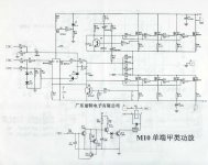
i have this schematic , collected from somewhere
is it similar - regarding protection ?
you said - you have protection circuit implemented on board
so , if I look at Aleph 30 schematic , I can't see schematic of missing part - protection
i have this schematic , collected from somewhere
is it similar - regarding protection ?
Attachments
please think
you said - you have protection circuit implemented on board
so , if I look at Aleph 30 schematic , I can't see schematic of missing part - protection
i have this schematic , collected from somewhere
is it similar - regarding protection ?
the protection circuit I bought from Jims_audio (indicated below the photo), I try to ask him if he can provide me the circuit.(but I think it will be very difficult)
An externally hosted image should be here but it was not working when we last tested it.
Uploaded with ImageShack.us
An externally hosted image should be here but it was not working when we last tested it.
Uploaded with ImageShack.us
ok - for now just exclude speaker protection ( but do not connect speaker to amp output)
post schematic here , which you're using and familiar with , and I'll mark what to measure
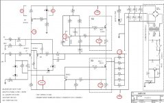
you mean the diagram of the amplifier? If so, the circuit is this:
View attachment Pass Aleph 30 Sch original.pdf
so - download this file , open it in MS Paint or some other graphic editor program , measure all red circle marked voltages in your actual circuit and write them on schmtc
then post it here
do not forget - both inputs grounded while testing
nothing connected to output
disconnect speaker protection circuit from amplifier for now
then post it here
do not forget - both inputs grounded while testing
nothing connected to output
disconnect speaker protection circuit from amplifier for now
Attachments
my power supply provides 23 volts, so you wonder if the values you have indicated no change;
however, if it can help you, I did a test and that is the extent of the offset : without signal, the measurement is 54mV, while inserting the plug XLR (even with the preamp off) the value increases to 0.54 V
NB: the protection circuit has been removed
however, if it can help you, I did a test and that is the extent of the offset : without signal, the measurement is 54mV, while inserting the plug XLR (even with the preamp off) the value increases to 0.54 V
NB: the protection circuit has been removed
do what I wrote - measure everything with red circle
there must be something - either broken part or wrong wiring
These are the measurements:
on resistor 221ohm 4,88 V (you post 5 V)
on zener 8,64 V (you post 9 V)
on drain IRF9610 (current generator for differential) 3,53 V (you post 4 V)
collector-emettitor ZTX450 UP 3,93 V (you post 4,5 V)
collector-emettitor ZTX450 DOWN 4,27 V (you post 4,5 V)
on first triplet resistor 0,47ohm : 0,40 V - 0,39 V - 0,38 V
on second triplet resistor 0,47ohm : 0,41 V - 0,38 V - 0,38 V
however, the thing that continues to leave me perplexed the fact remains that if not connect the signal, the output voltage is around 40mV, while connecting the signal rises to 0.54 V, hence the reason for which the speaker protection (which currently is disconnected) goes in protection.
so , after several posts - I'm realizing that your problem is combined from two things :
1-unmatched input mosfets
2-missing procedure/possibility for setting output offset
cure :
replace R11 with 500R multiturn trimpot (connected as variable resistor - middle leg connected with one (any) outer leg)
set it , prior to soldering , to half value
short both inputs to ground
power up
set offset with that trimpot , after temperature equilibrium
do the same for other channel
shorting inputs to gnd during setting offset and Iq procedure is a must
- Status
- This old topic is closed. If you want to reopen this topic, contact a moderator using the "Report Post" button.
- Home
- Amplifiers
- Pass Labs
- please help me