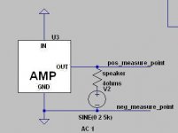
basically, short the input, put a speaker driver in series with the live output, test signal applied to the negative side of the driver, data taken from the live output side of the amp.Sorry ,can someone explain what these graphs is showing ?
How the graphs are done and how is the measurement done ?
Thank you !
To answer your question, yes and no. To elaborate on it would be like writing a book, a task I am not prepared to do at this time. But you have to know whether you can trust your own results depending on what kind of amplifier you use and how you are going to use the results. There is no perfectly ideal test setup, there is only test setup adequate for specific purposes.
Dario,
What ever happened with the investigation of the decoupling of the LM318?
I am late to this thread and have only read the last 50 pages or so. And I have not yet built one of these amplifiers.
Just thinking in general terms, though, I could calculate an estimate of the maximum tolerable inductance (i.e. total trace length plus cap lead-spacing) for the decoupling, there, as well as the minimum cap value and maximum tolerable ESR, given the worst-case current amplitudes and frequencies involved. (The lowest impedance up to the highest frequency is always best, there. But calculations might suggest that the existing trace lengths do not meet minimum requirements.)
I am fairly sure that you won't like hearing the following, but: it seems likely, to me, that AndrewT was on the best path toward thinking the most-correctly about the decoupling issue: For the high-frequency portion of the decoupling, almost nothing else matters except using the largest value available in the physically-smallest (or "small-enough") cap case-size and, especially, the physically-shortest path, in order to have the lowest-possible inductance. And it is critical to do that.
Aside: (I read where you asked for definitions. This is my take-away, having done a lot of studying of decoupling and bypassing literature, over the years: ) "Decoupling" is when the cap acts much like a small local power supply, supplying the fast transient currents that are demanded/allowed by the power pins. The main reason for decoupling caps is so that those fast transient currents don't have to attempt to travel through the inductance of the power and ground rails, which would create a voltage spike on the rails (as well as impair performance). Decoupling caps attempt to decouple some local power distribution point's dynamics from the rest of the power distribution network. "Bypassing" is when the cap acts as a short circuit for high frequencies that might feed back through the power rails, to short (i.e. bypass) the HF to ground, to mitigate the hidden HF positive feedback path through the power rail, which exists in most transistor-based amplifier circuits.
Taking the C7 traces out to a location next to the end of the LM318's case, as in the last PCB image I've seen, most-likely significantly degrades the decoupling effectiveness at higher frequencies, with possible effects on feedback effectiveness and, among other things, transient response accuracy, which could directly affect imaging.
That cap also performs HF bypass duty, to prevent HF oscillation and ringing.
For both of those purposes, the total distance from pin to pin, through the cap, needs to be absolutely as short as possible. Adding 2 mm is considered to be significant, there, for example. (And a socket would certainly muddy the waters.)
Is there some reason that optional more-direct traces cannot also be provided, on the bottom of the board? A layout that was both through-hole and surface-mount-compatible, for that optional cap location, would be ideal (check footprints for 470 nF X7R surface-mount types?). (Through-hole might be "interesting", but might be possible if installed before the LM318. Or, a through-hole part could be surface-mounted.)
In that case, the existing traces and mounting location could be kept as is, and could be used for an optional physically-larger parallel decoupling cap, which could provide benefits in the medium and/or lower frequency ranges, and further opportunities for optimizing the amplifier's response.
And, separate from all of the above, have you thought any more about AndrewT's suggestion of decoupling each pin to ground, separately?
Respectfully,
Tom
Last edited:
Tom, thanks so much for your definition explanations. It's the clearest I have read to date. I'm really glad to finally see you here - welcome. Some of what you suggest may have been incorporated in Dario's FE design, but I imagine he will most likely comment here as it's the base thread for the MyRefs. Not sure what changes are in store for the final version of the FE and/or linuxguru's dual LM3886 design, but hopefully we will soon get that information.
You are welcome, Bob. But if you get right down to it, the terms are often used interchangeably and the "definitions" are just my opinion of "how it ought to be".

The LM318 section uses rail-to-ground decoupling with electrolytics C6 and C11, and rail-to-rail HF bypassing with film cap C7, respectively. Early on, it was empirically observed that a rail-to-ground HF bypass of the electrolytics with small film caps actually made the audible sonics worse. I'm not sure why this is the case.
Subsequently, Dario empricially found and others independently confirmed that C7 was critical to audible sonics. A smaller value in the range of 5nF to 22nF, and the highest quality that would physically fit in the space provided, empirically seemed to improve the sonics greatly. The best results have been found with film/foil types like FKP, FKS, FKC, ER0 KP1837, RIFA PFE225 and similar.
There have been two approaches to mitigating the the trace inductance of C7, apart from keeping the leads short.
1. Use a ground-plane on one side and treat the traces to C7 as microstrip transmission lines.
2. Use multiple thin traces in parallel to reduce the combined L, which also benefits from opposing magnetic-field cancellation between the thin traces.
(Both approaches above can also be combined, which I've tried in the V1.4 PCB for the MyRef).
However, not much can be done about the lead inductance within the package of C7. Stacked film-foil has an advantage here compared to cylindrical wound types.
In SMD, the choices are limited to C0G ceramic and Panasonic ECHU (which is stacked film-foil polyphenylene sulphide) for C7. However, since C7 is rail-to-rail, the more common 16V-rated ECHU is inadequate and 50V parts are required here. The good news is that 22nF/50V is available in 1210 size, and this may also work well at C21 (optional HF bypass for C9).
I have not auditioned the ECHUs at either C7 or C21 - I just acquired a few recently, for use in CD player upgrades. Based on preliminary auditioning of a Marantz CD4000 with ECHUs, I believe that it is very promising for MyRefs also.
The LM318 section uses rail-to-ground decoupling with electrolytics C6 and C11, and rail-to-rail HF bypassing with film cap C7, respectively. Early on, it was empirically observed that a rail-to-ground HF bypass of the electrolytics with small film caps actually made the audible sonics worse. I'm not sure why this is the case.
Subsequently, Dario empricially found and others independently confirmed that C7 was critical to audible sonics. A smaller value in the range of 5nF to 22nF, and the highest quality that would physically fit in the space provided, empirically seemed to improve the sonics greatly. The best results have been found with film/foil types like FKP, FKS, FKC, ER0 KP1837, RIFA PFE225 and similar.
There have been two approaches to mitigating the the trace inductance of C7, apart from keeping the leads short.
1. Use a ground-plane on one side and treat the traces to C7 as microstrip transmission lines.
2. Use multiple thin traces in parallel to reduce the combined L, which also benefits from opposing magnetic-field cancellation between the thin traces.
(Both approaches above can also be combined, which I've tried in the V1.4 PCB for the MyRef).
However, not much can be done about the lead inductance within the package of C7. Stacked film-foil has an advantage here compared to cylindrical wound types.
In SMD, the choices are limited to C0G ceramic and Panasonic ECHU (which is stacked film-foil polyphenylene sulphide) for C7. However, since C7 is rail-to-rail, the more common 16V-rated ECHU is inadequate and 50V parts are required here. The good news is that 22nF/50V is available in 1210 size, and this may also work well at C21 (optional HF bypass for C9).
I have not auditioned the ECHUs at either C7 or C21 - I just acquired a few recently, for use in CD player upgrades. Based on preliminary auditioning of a Marantz CD4000 with ECHUs, I believe that it is very promising for MyRefs also.
Thanks, linuxguru. That filled in a lot of the gaps in the picture I had of the situation. (Edit: Make sure that you read this post all the way to the end.)
It's not surprising that paralleling small film caps with electrolytics caused a problem. That horse was beaten to death, here in this forum: http://www.diyaudio.com/forums/power-supplies/106648-paralleling-film-caps-electrolytic-caps.html .
Everyone agreed that paralleling electrolytics with film caps was very risky. The film caps are not lossy-enough (i.e. ESR is too low) and can create high-Q resonant LC tank circuits with the parasitic inductance of the electrolytic caps. (Hint: It would be good if someone would try X7R ceramic caps, there, with 470 nF to 100 nF per pin.)
Note that C0G and NPO ceramics are usually specifically NOT recommended for use as bypass or decoupling caps, because they too are not lossy-enough to damp any such resonance that might be formed when they are paralleled with an electrolytic, or some other parasitic inductance. Along with the resonant LC tank, you would get an impedance peak at a frequency between the impedance dips of the two paralleled caps. Not good.
I am very glad to hear that someone was actually trying to lower the inductance of the connections for C7. Were any inductance or impedance measurements taken (from the point of view of the chip pins)? Was any audible difference noted? Were any oscilloscope captures performed, with fast signal edges present, to compare the different trace configurations?
By the way, capacitors' inductances are almost always only due to their lead-spacing distance. Any good-quality "cylindrically wound" cap will NOT have any more inductance than any other type of cap. The good ones are not wound as coils, with only the ends of the windings connected! The connections are made ALL ALONG ONE EDGE of each winding. So there is ZERO "coil" effect. (They offset the two strips of foil, so that the edge of one sticks out farther on one end of the roll and the edge of the other one sticks out farther on the other end of the roll. Then, after winding, they press a metal cap against each end of the roll, contacting the entire edge of each foil strip. There is no inductive coil effect.)
Why do you say that the SMD choices for ceramic are limited to C0G and NPO? The X7R type is what is always recommended, for decoupling and bypassing, for the reasons given above, i.e. ESR should not be too low or LC resonance problems can too-easily result.
Does everyone here believe that super-LOW ESR is always good, and film caps are always better than ceramic??? Sorry but those are NOT true statements.
But that gives me a CLUE, and an idea. It is unlikely, but, if true, the implications would be very important for your efforts:
COULD it be POSSIBLE that, because almost everyone involved was ONLY experimenting with their beloved FILM types of caps, that THAT is the reason that they "found that C7 was critical to audible sonics"??
C7 should probably NOT be so critical to the sound quality, unless MAYBE the film caps were usually forming LC resonances with the trace inductances, and/or some other stray inductance, and everyone was simply evaluating the changes in sound quality due to various different parasitic high-frequency RESONANCE PROBLEMS, or even just changes in sound quality due to HF oscillations or ringing that were caused by instability or marginal stability!
INDEED, that (or something similar) now seems like a NOT-TOO-UNLIKELY scenario, especially since the MyRef circuit is basically a Howland Current Pump topology, which has always had a reputation for stability difficulties, since it uses both positive and negative feedback.
THE BOTTOM LINE: While it's just a theory, at this point, it looks like the unexpected over-sensitivity of the sound quality to the type and value of C7 might be pointing out that something (very-possibly the decoupling/bypassing layout and maybe the types/values of decoupling/bypass caps used) might have put the amplifier right on the edge of instability, at some frequency or frequencies.
It could be ringing or even oscillating at some very high (RF or RF-like) frequencies, under certain conditions, which could cause anything from very subtle to not-so-subtle effects on the audio at the output, with effects that would be very difficult to predict.
If someone has a good high-frequency oscilloscope, or an RF spectrum analyzer, they might be able to determine if that is the case.
But I think that I would at least temporarily try a PROPER decoupling and bypassing configuration, for both chips in a channel, and then check to see if the sound quality is still so sensitive to C7.
I'm not sure if Bob Pease's analysis of Howland current sources mentioned any special considerations for decoupling or bypassing, or not. I think it was AN-1515 at National.com. But a search there for "howland" should quickly find it.
If he didn't mention any tips for decoupling, bypassing, or stability, then I would first try the standard classic recommended techniques (for which there are VERY good reasons and which typically do NOT include any FILM cap). i.e. (Usually, but not always: ) Place a ceramic X7R directly AT each power pin and connect the other end to the amp load's ground, and place a parallel electrolytic also directly at each power pin, and to the same ground. A first try for the X7R ceramic's value should probably be 470 nF, but a physically-smaller X7R, possibly with a lower value, could and probably should also be placed in parallel. The smallest cap should be attached closest to the pin (and closest to the IC's case), if they can't all be as close for some reason (but try very hard). The electrolytic should be at LEAST 10 uF, but larger is probably always better. However, only use a value that has a case size that can still fit where the cap can attach directly AT the IC pin. Larger electrolytics can still also be added, farher away, but only farther away by the smallest-possible distance. If there is more than two centimeters or so, between a power pin and the decoupling/bypass ground connection, then use three of each cap in parallel, to lower the impedance.
Last edited:
Thanks for the link to the thread, and your comments. I'll need some time to read and digest the info in that thread, so I'll confine myself right now to just one observation on some wound cylindrical film-foil caps: the construction on most cheap styroflex caps consists of just the lead wires stuck in contact with each foil *at just one layer* and the foil-film-foil sandwich is just rolled until sufficent capacitance has been aggregated. Note that the internal resistance in this construction may include the resistance of the entire length of foil (if the leads are both at one end of each foil). The same holds for the inductance, but due to the anti-parallel direction of current flow in the two foils, foil inductance may partially cancel out as a happy coincidence - again depending out the location of the two leads wrt to the foil.
Stacked film-foil, e.g. FKP2, eliminates uncertainties of this kind and has dependably low and consistent ESR and ESL. Not surprisingly, it also sounds very good at C7.
Stacked film-foil, e.g. FKP2, eliminates uncertainties of this kind and has dependably low and consistent ESR and ESL. Not surprisingly, it also sounds very good at C7.
Last edited:
I think the voltage/current gain combination needs to match the load impedance. So it should vary depending on speaker impedance for optimum performance. I did a little test a while back, and the sound was much cleaner and less colored. However, I had not the time to follow up on measurements.
Thanks for the link to the thread, and your comments. I'll need some time to read and digest the info in that thread, so I'll confine myself right now to just one observation on some wound cylindrical film-foil caps: the construction on most cheap styroflex caps consists of just the lead wires stuck in contact with each foil *at just one layer* and the foil-film-foil sandwich is just rolled until sufficent capacitance has been aggregated. Note that the internal resistance in this construction may include the resistance of the entire length of foil (if the leads are both at one end of each foil). The same holds for the inductance, but due to the anti-parallel direction of current flow in the two foils, foil inductance may partially cancel out as a happy coincidence - again depending out the location of the two leads wrt to the foil.
Stacked film-foil, e.g. FKP2, eliminates uncertainties of this kind and has dependably low and consistent ESR and ESL. Not surprisingly, it also sounds very good at C7.
linuxguru,
Sorry. I meant to insert a comment stating that I didn't think you should feel the need to read that whole thread (unless you're just interested, of course), just for this discussion. It is quite a long thread, with some areas of "spinning of wheels" (not getting anywhere). But it is still well worth reading. Later in that thread, you'll even run across my first attempts at calculating minimum values for decoupling capacitors and their maximum-acceptable connection lengths, etc.
On the wound caps: I was aware of the types that are manufactured as you described but have never used those types. My main point there was supposed to be that most, or at least many, types of wound film caps would not be badly implemented, like that.
My whole post was basically just "shooting from the hip", maybe even sometimes with eyes closed.
") So (if you are even interested) please feel free to casually poke holes wherever you see an opportunity, and we will see what I can keep from falling apart, and maybe something helpful will come out of it.
So (if you are even interested) please feel free to casually poke holes wherever you see an opportunity, and we will see what I can keep from falling apart, and maybe something helpful will come out of it.The entire last half or more (of my post) was a possibly-crazy idea that somehow just came to me, way after I had started writing the post. It's based only on a gut feeling and a wild guess. (But sometimes I get pretty lucky.) [I decided to go ahead and post it, anyway, because in terms of Risk Assessment, even very-low-probability possibilities should still be considered to be possibly-significant if their potential consequences contribute enough weighting to their "probability x consquences" product term.]
Even if I was wrong about most of the whole last part of my post, I still think that there might be something going on that the C7 behavior might relate to, that might need to be investigated. I read most of the descriptions of the effects on sound quality of different choices for C7 and they all seem to not be inconsistent with a possible marginal stability problem (or maybe even something kind-of strange, like a SpiKE-related effect being triggered by HF artifacts). But there's no way to know, at this point, if there is even a problem.
Maybe I should have simply said that since apparently no one knows why the circuit is so sensitive to what is used for C7, we might want to try to determine the reason, just in case it is a symptom of something that might need to be improved.
Has anyone posted a really-good spice model for this circuit? If so, some insight might be gained by performing some type of sensitivity analysis involving C7 (et al) and certain PCB-trace parasitics. Isn't there now a decent LM3886 spice model available? Or was I only dreaming?
I did a lot of LT-Spice simulations of a voltage-controlled Improved-Howland current source, with a discrete (push-pull) booster amplifier inside the feedback loops, for a piece of test equipment I designed, "several" years ago.
So, if some type of simulation studies were deemed to be potentially helpful to you, then I would be happy to try to contribute.
Cheers,
Tom
Last edited:
Hi Tom
Well, the most interesting part lies in the first 50 pages, where the designer (Penasa) introduced his project.
Maybe you'll partecipate to the upcoming Fremen Edition GB
No problems about it...
In the FE the path is the shortest possible with TH parts:
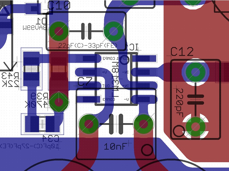
An SMD part would not make a great difference on traces lenght...
Regarding sockets I do agree they can make a difference in the effectiveness of the decoupling/bypassing (choose your favourite name) but I can't see a more effective way to compare among different parts... suggestions are always welcome
I do agree but the Twisted Pear monoblock design it's not mine...
In fact, as you have already seen in the previous picture, I've designed a new board also for this reason.
Using an SMD LM318 a TH C7 can be arranged not much differently than an SMD one...
Sincerely no.
For two main reasons:
Hi Siva,
this is not exact, while the FE makes large use of quasi-microstrips it's not the case of C7.
(End of first part)
I am late to this thread and have only read the last 50 pages or so. And I have not yet built one of these amplifiers.
Well, the most interesting part lies in the first 50 pages, where the designer (Penasa) introduced his project.
Maybe you'll partecipate to the upcoming Fremen Edition GB
I am fairly sure that you won't like hearing the following, but: it seems likely, to me, that AndrewT was on the best path toward thinking the most-correctly about the decoupling issue: For the high-frequency portion of the decoupling, almost nothing else matters except using the largest value available in the physically-smallest (or "small-enough") cap case-size and, especially, the physically-shortest path, in order to have the lowest-possible inductance. And it is critical to do that.
(...)
For both of those purposes, the total distance from pin to pin, through the cap, needs to be absolutely as short as possible. Adding 2 mm is considered to be significant, there, for example. (And a socket would certainly muddy the waters.
No problems about it...
In the FE the path is the shortest possible with TH parts:
An SMD part would not make a great difference on traces lenght...
Regarding sockets I do agree they can make a difference in the effectiveness of the decoupling/bypassing (choose your favourite name) but I can't see a more effective way to compare among different parts... suggestions are always welcome
Is there some reason that optional more-direct traces cannot also be provided, on the bottom of the board? A layout that was both through-hole and surface-mount-compatible, for that optional cap location, would be ideal (check footprints for 470 nF X7R surface-mount types?). (Through-hole might be "interesting", but might be possible if installed before the LM318. Or, a through-hole part could be surface-mounted.)
I do agree but the Twisted Pear monoblock design it's not mine...
In fact, as you have already seen in the previous picture, I've designed a new board also for this reason.
Using an SMD LM318 a TH C7 can be arranged not much differently than an SMD one...
And, separate from all of the above, have you thought any more about AndrewT's suggestion of decoupling each pin to ground, separately?
Sincerely no.
For two main reasons:
- the original designer thought they were not necessary, if not detrimental, since both opamps are already decoupled/bypassed R2R which is, accornding him, the preferred way
- in my empirical tests the rail to ground decoupling caps were always detrimental to sound (X7R ceramics were the most transparent, though)
There have been two approaches to mitigating the the trace inductance of C7, apart from keeping the leads short.
1. Use a ground-plane on one side and treat the traces to C7 as microstrip transmission lines.
Hi Siva,
this is not exact, while the FE makes large use of quasi-microstrips it's not the case of C7.
(End of first part)
Attachments
(Second part)
Sure, my experience was the same, most of the times the most transparent bypass for a larger cap was an X7R ceramic.
As you've already read I've already did such test with the My_Ref.
Sadly, not.
I don't have the necessary instrumentation and, BTW, the FE boards have a lot of other improvements... hard to tell ...
I do agree
Simply: NO
I've tried ceramics for decoupling and for C7, in this case they didn't their 'magic'
But in fact it's so, I don't have the knowledge to judge Mauro's compensation but I trust his competence.
Everyone agreed that paralleling electrolytics with film caps was very risky.
(...)
(Hint: It would be good if someone would try X7R ceramic caps, there, with 470 nF to 100 nF per pin.)
Sure, my experience was the same, most of the times the most transparent bypass for a larger cap was an X7R ceramic.
As you've already read I've already did such test with the My_Ref.
I am very glad to hear that someone was actually trying to lower the inductance of the connections for C7. Were any inductance or impedance measurements taken (from the point of view of the chip pins)? Was any audible difference noted? Were any oscilloscope captures performed, with fast signal edges present, to compare the different trace configurations?
Sadly, not.
I don't have the necessary instrumentation and, BTW, the FE boards have a lot of other improvements... hard to tell ...
Does everyone here believe that super-LOW ESR is always good, and film caps are always better than ceramic??? Sorry but those are NOT true statements.
I do agree
COULD it be POSSIBLE that, because almost everyone involved was ONLY experimenting with their beloved FILM types of caps, that THAT is the reason that they "found that C7 was critical to audible sonics"??
Simply: NO
I've tried ceramics for decoupling and for C7, in this case they didn't their 'magic'
C7 should probably NOT be so critical to the sound quality,
(...)
INDEED, that (or something similar) now seems like a NOT-TOO-UNLIKELY scenario, especially since the MyRef circuit is basically a Howland Current Pump topology, which has always had a reputation for stability difficulties, since it uses both positive and negative feedback.
But in fact it's so, I don't have the knowledge to judge Mauro's compensation but I trust his competence.
"Has anyone posted a really-good spice model for this circuit? If so, some insight might be gained by performing some type of sensitivity analysis involving C7 (et al) and certain PCB-trace parasitics. Isn't there now a decent LM3886 spice model available? Or was I only dreaming?"
I've been tryng to, at a minimum, collect all the FE components into a couple highly sophisticated simulation programs. Don't know what success I have - it's like a bee keeper trying to fix the engine in a Mercedes. Giant Knowledge Gap !!
I've been tryng to, at a minimum, collect all the FE components into a couple highly sophisticated simulation programs. Don't know what success I have - it's like a bee keeper trying to fix the engine in a Mercedes.
Giant Knowledge Gap !!
Last edited:
- Home
- Amplifiers
- Chip Amps
- My "audiophile" LM3886 approach