Hi! I have another power supply related question that deserved its own topic.
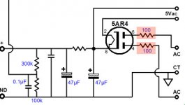
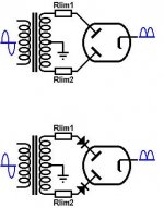
I hear a lot about anode treatments to protect the rectifier but I am not entirely sure what is the best safe to longevity to ear ratio. The power supply design I'm using recommends on each plate to put a 100ohm resistor in series. The yellow page recommends not resistors, but diodes in series with each plate. The Valve wizard brings up every scenario ever made including the hybrid of the two; A limiting resistor with diodes.
Im using a Sovtek 5AR4… and has been noted to be not the most robust of all designs. Diodes recommended?
Im also trying to figure out if me putting resistors and diodes is gonna limit my B+ voltage much.
I have a 210V-0-210V transformer and I'm roughly shooting for 300…
I know I'm gonna be under a bit, but not a show stopper.
Anyone got any entry level tips for not blowing myself up?
-edit:
I really mean limiter tips..
Attachments
Last edited:
I can't seem to find Sovteks 5ar4 to find recomended anode limit resistor values... But it looks like from the tube cad site that 100ohms per leg looks like a general rule of thumb for dealing with inrush current. First off... Does it really work for those starting spikes? Or does it just drop the overall voyage more than anything else.
Even though I won't be pushing the rectifier to its limits, I do feel that putting some safety diodes in there won't hurt correct? It won't destroy the sag attributes of the tube and it definitely will prolong the life of the tube yes?
A hybrid of the two is wrong? Or is it too safe
Even though I won't be pushing the rectifier to its limits, I do feel that putting some safety diodes in there won't hurt correct? It won't destroy the sag attributes of the tube and it definitely will prolong the life of the tube yes?
A hybrid of the two is wrong? Or is it too safe
Also in addition:
http://www.svetlana.com/pdf/sovtek/5ar4-sovtek.pdf
ok, found sovteks 5ar4 datsheet. Looks like I dont have a capacitor or choke input. Being that this is off of a transformer... do I treat this as a capacitor input?
If so, my RMS is about 210Vac which is below their charted resistor values. But judging by what comes next, looks like I would need a 30ohm limiting resistor?
Looks like I dont have a capacitor or choke input. Being that this is off of a transformer... do I treat this as a capacitor input?
Uhm, you definitely have a capacitor-input circuit, if the first diagram you posted is the one you're using.
The term xxx-input refers to the first filter element that follows after the rectifier. Is it a cap, as in your case, the PS is capacitor-input, if it is a choke - then it's choke-input.
The datasheet lists the recommended values for the resistors in the anode leads, just choose the value that fits your operating conditions. And don't forget to take into account the secondary resistance of the transformer. If you need as low as 30 ohms, maybe you get away with the secondary resistance (along with the reflected primary resistance, which has to be taken into account as well). Look for 5AR4 datasheets of older 'real' tube manufacturers, they often give more detailed information on the calculation of that resistance.
Greetings,
Andreas
Last edited:
The 'input' referred to is the first component after the rectifier, so you have capacitor input. I would say you don't need a resistor or diode, as you are running well inside the rectifier spec. The transformer secondary resistance will be much bigger than 30 ohms anyway.
That 'sovtek' sheet is actually just a photocopy of a standard US datasheet - RCA or Sylvania?
That 'sovtek' sheet is actually just a photocopy of a standard US datasheet - RCA or Sylvania?
Ahh! That makes more sense... misleading terminology though. This is good!
How do I measure the transformers secondary resistance? Just across the leads? Its a Center Tap (center out?). Or is it as vague as measuring speaker impedance.
But looks like I dont have to do anything... but it cant hurt to throw in a safety diode just in case ya?
How do I measure the transformers secondary resistance? Just across the leads? Its a Center Tap (center out?). Or is it as vague as measuring speaker impedance.
But looks like I dont have to do anything... but it cant hurt to throw in a safety diode just in case ya?
Measure secondary from CT to ends and take the average, as they are likely to be slightly different. Then add on transformed primary resistance too.
The cap or choke input terminology is not misleading if you regard it as describing what the input of the PSU smoothing stages looks like when seen from the rectifier.
A safety diode, being unnecessary, merely adds one more component which could fail.
The cap or choke input terminology is not misleading if you regard it as describing what the input of the PSU smoothing stages looks like when seen from the rectifier.
A safety diode, being unnecessary, merely adds one more component which could fail.
Cool, screw diodes anyway. That's why I chose the rectifire in the first place. So I measured the resistance of the center tap and read 90ohms averaged from both legs. And read from the primary side 8ohms per 120v section. Being that I'm using 120v, I will be running the primary in paralell making it 4 ohms.
So 90 + 4 = 94 ohms! I think that's a healthy enough resistance for the rectifier ya? Does this sound right? Seems like it to me.
Also bonus side question; has anyone used a power transformer as an output transformer? I would like to say that you could do impedance matching etc. could you run something through a power transformer that is not 50 or 60 Hz? They are all made out of similar meat and potatoes right?
No. The primary resistance is reflected to the secondary. You need to multiply it by the square of the turns ratio.Cool, screw diodes anyway. That's why I chose the rectifire in the first place. So I measured the resistance of the center tap and read 90ohms averaged from both legs. And read from the primary side 8ohms per 120v section. Being that I'm using 120v, I will be running the primary in paralell making it 4 ohms.
So 90 + 4 = 94 ohms! I think that's a healthy enough resistance for the rectifier ya? Does this sound right? Seems like it to me.
90 + ((210/120)^2)*4
90 + (1.75^2)*4
90 + (3.0625)*4
90 + 12.25
102.25
In my opinion you need neither the resistor or the diode.
Last edited:
Hey there,
FoMoCo was faster than me, regarding the correction of the reflected primary impedance")
I am not sure if I understood you right, but if the secondary impedance is 90 ohms in each leg (from center tap to *each* end of secondary winding), then you're safe. If 90 ohms is the total resistance of the secondary (end to end), then it might be a bit low and need resistors.
Greetings,
Andreas
FoMoCo was faster than me, regarding the correction of the reflected primary impedance
I am not sure if I understood you right, but if the secondary impedance is 90 ohms in each leg (from center tap to *each* end of secondary winding), then you're safe. If 90 ohms is the total resistance of the secondary (end to end), then it might be a bit low and need resistors.
Greetings,
Andreas
I took it as he measured from center-tap to each leg and then averaged the two readings. If, indeed, the 90 ohms was the entire secondary, then I have to second Rundmaus'. Some resistance may be required.Hey there,
FoMoCo was faster than me, regarding the correction of the reflected primary impedance
I am not sure if I understood you right, but if the secondary impedance is 90 ohms in each leg (from center tap to *each* end of secondary winding), then you're safe. If 90 ohms is the total resistance of the secondary (end to end), then it might be a bit low and need resistors.
Greetings,
Andreas
Tube rectifiers has been working fine several decades without diodes nor resistors. Thousands of radios, TV and amplifiers are the evidence of it.
The only rectifier that almost always uses a resistor of about 50R was in the half wave rectifiers like 35Z5 or 35W4 who operates directly from power cord.
I only suggest to include a fuse in the center leg of the transformer to the chassis in order to prevent any short circuit.
The only rectifier that almost always uses a resistor of about 50R was in the half wave rectifiers like 35Z5 or 35W4 who operates directly from power cord.
I only suggest to include a fuse in the center leg of the transformer to the chassis in order to prevent any short circuit.
Last edited:
Of course, and also more resistance reflected from primary, given the step up voltage transformer ratio, and also lowest winding (Copper) and core (Iron) quality (And higher looses), all of them can also be reflected as resistance in secondary or primary side, although is more common to reflect them into primary side.
Oh! This is totally news to me. Thank god I asked you guys this.
The transformer resistance formula is a good thing to know (Never saw it before). I measured the ct to one leg at a time and averaged their two ohm values so all looks right.
So it looks like I don't need anything on the legs! nice!
I was gonna ask about the fuse eventually. Is it smarter to put it on the primary side or the CT of the secondary? Origionaly I was gonna put it after the switch on one lead.
I'd put it on the primary side. Otherwise the fuse doesn't protect the transformer.
Putting it on the secondary subjects it to higher voltage. You'd also need two fuses, one before each rectifier. The center tap is particularly a bad idea. If one of your rectifiers shorts, it doesn't protect at all against that.
No offense. But, it seems that maybe you shouldn't be playing around with high voltage at this stage of the game.
Im following these schematics pretty closely but also at the same time, Im getting a lot of unique tips that defy the schematics. Such as LimR values, transformer resistance & fuse placement (as mentioned above). I understand the danger of high voltage but thats why I am raising these questions in the first place.
Place the fuse on the hot side and before the switch, that way if the switch develops a short to chassis (I have seen it happen) the local fuse can blow rather than relying on a distant circuit breaker to protect the intervening wiring. Make sure that the chassis is grounded.
I use the series diodes with all modern 5AR4 as it greatly reduces their propensity to fail due to arcing during warm up and during a hot start event. (Supply interruption)
I use the series diodes with all modern 5AR4 as it greatly reduces their propensity to fail due to arcing during warm up and during a hot start event. (Supply interruption)
- Status
- This old topic is closed. If you want to reopen this topic, contact a moderator using the "Report Post" button.
- Home
- Amplifiers
- Power Supplies
- Tube Rectifier Limiter