Hi,
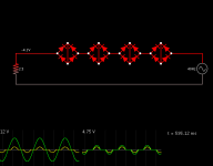
I am currently constructing a preamp with a 5AR4 rectifier and ran into the issue of needing to convert the 12vac secondary to 5vac to run the filament of the 5ar4 to start up the whole system.
Long story short, I had to utilize the 6.3vac output of the transformer for supplying the regular heater lines. the remaining secondary for the main tube rectifier is a 12v @ 2A line. I dont have space for another (115v to 5v) transformer. I am currently looking for a 12vac to 5vac transformer (hopefully smaller than 115:5).
Another method that can be much smaller is SS rectifying the 12vac and voltage dividing the created DC. not bad...
another method is :
AC Voltage Dropper
the peak is scaled down nicely to 5v... but the RMS would be some pathetic 3v due to the incredible notching created by diode rectifying. Anyone know how to smooth out the output to raise the RMS to a realistic sinewave?
another method could be using resistors to stomp down the 12V... but it could get hot(?) Also, would this draw more Amps? My transformer can only put out 2A @ 12V. I dont mind heat from the resistors too much.. but I def dont want to over saturate the transformer.
Hopefully I am not all that screwed over. Any tips?
Attachments
If you can get the values right consider a wattless dropper by using the reactance of a capacitor to drop the voltage. Or a combination of C and R.
Series resistors are fine and the current drawn is the same as the filament on its correct voltage... its just a series circuit.
Series resistors are fine and the current drawn is the same as the filament on its correct voltage... its just a series circuit.
Its an old technique...
I can't really see there being an issue in practice. I'm just trying to visualise whether the current in the cap being 90 degrees out of phase with the voltage is an issue... and how it relates to the inductance of the transformer.
It just relies on the capacitive reactance of the cap (a sort of AC resistance value).
xc= 1/2*pi*f*c
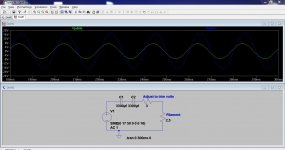
I choose two caps in series because thats how a normally non polarised cap is constructed from two electrolytics but I'm thinking do we need that. There is no DC or DC bias and so I can't see why one cap wouldn't be OK.
I can't really see there being an issue in practice. I'm just trying to visualise whether the current in the cap being 90 degrees out of phase with the voltage is an issue... and how it relates to the inductance of the transformer.
It just relies on the capacitive reactance of the cap (a sort of AC resistance value).
xc= 1/2*pi*f*c
I choose two caps in series because thats how a normally non polarised cap is constructed from two electrolytics but I'm thinking do we need that. There is no DC or DC bias and so I can't see why one cap wouldn't be OK.
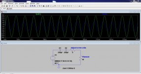
Here's with a single cap.
Practical points. Maybe use two or three parallel caps to split the current. 2 amps RMS is within a typical good quality caps spec (typically around 2800ma but check the data sheet for any caps used) but it makes sense to make it easier for the caps. Two 2200 uf give 4400uf total. Or three 1000uf caps. Adjust the resistor to suit.
Transformer dissipation wise I think its OK. It's a series circuit and the "real" power and current is dissipated in the resistances. There will be a theoretical ah but aspect which depends on the inductance of the transformer but I think its OK.
Practical points. Maybe use two or three parallel caps to split the current. 2 amps RMS is within a typical good quality caps spec (typically around 2800ma but check the data sheet for any caps used) but it makes sense to make it easier for the caps. Two 2200 uf give 4400uf total. Or three 1000uf caps. Adjust the resistor to suit.
Transformer dissipation wise I think its OK. It's a series circuit and the "real" power and current is dissipated in the resistances. There will be a theoretical ah but
aspect which depends on the inductance of the transformer but I think its OK.Attachments
I'd try to adjust with capacitors rather than a resistor. After going the trouble of reactive current source to being with, why have more lost in an adjustment R than in the load?. Go low with the value of the main cap bank by a few 100u and then tack on required small value in parallel to dial in if necessary. Probably should look for a couple times the ripple current capacity in the caps than the actual load, if the caps are expected to last as long as the transformer. I don't think the transformer would complain about the current phase shift any more than the limited conduction angle method, and the caps will make a lot less noise.
Do you have an idea about the tanδ of real lytics? I mean the ones with messy things inside, like paper soaked in liquid chemicals, porous layers of dielectrics and aluminium, etc, not the polcap from LTspice.I can't really see a practical problem either with the phase shift and dissipation.
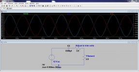
Reactive power is something like 12VAR in this case, I let you make the calculations and guess the result:

This is truly fascinating. Using the capacitors natural impedance to limit. I love the idea of truly minimized heat / wattage consumption.
I realized that this is a job for electrolytics being a high uF number. Afraid as usual about the negative terminal seeing potential positive current, I would be one to say I must have another electrolytic to block the negative side. But you mentioned that I don't need to in this case because of the lack of DC present? What precisely is going on and should I sweat about it?
I realized that this is a job for electrolytics being a high uF number. Afraid as usual about the negative terminal seeing potential positive current, I would be one to say I must have another electrolytic to block the negative side. But you mentioned that I don't need to in this case because of the lack of DC present? What precisely is going on and should I sweat about it?
Last edited:
It can be made to last. I doubt it can be made much smaller than a dedicated transformer, though.
Type A series Bi-polar SU | Aluminum Electrolytic Capacitors/Conductive Polymer Hybrid | Passive & Electromechanical | Industrial Devices | Panasonic Global
Type A series Bi-polar SU | Aluminum Electrolytic Capacitors/Conductive Polymer Hybrid | Passive & Electromechanical | Industrial Devices | Panasonic Global
Even with this high-tech, bipolar example, it would be difficult to make it last.It can be made to last. I doubt it can be made much smaller than a dedicated transformer, though.
Type A series Bi-polar SU | Aluminum Electrolytic Capacitors/Conductive Polymer Hybrid | Passive & Electromechanical | Industrial Devices | Panasonic Global
Normally, you would choose the 1000µF/10V for this application.
Since it is obviously inadequate, you would jump two size and go for the 25V.
But it only tolerates 680mA @120Hz. That is still far from 1.9A, and the spec is at 120Hz. For 50Hz, the duty is much harder.
In this series, you would have to parallel 10 100µ/35V just to arrive at the minimal life of 2000H.
With standard quality caps, that would be even harder.
This is somewhat new news to me as we'll. electrolytics have a amp to Hz rating? If I just oversized the volt rating to something higher, would it make my time more worthwhile? A small transformer couldn't easily fit into my layout... But I can manage capacitors being sprinkled all about.
Any tips on how to properly use capacitors?
Any tips on how to properly use capacitors?
But I can manage capacitors being sprinkled all about.
Elvee is right. You would need a very large bank of caps to make this reliable. The cost and size (size even more than cost) would be way above a simple 10 VA transformer. It wouldn't make sense. Try a Hammond 166L5.
Last edited:
Oh dang! That would be an unreasonable solution. Longevity is important.
So as a worst case scenario, I will end up getting that Hammond 5Vac CT transformer.
But in next best bet.. (Being that capacitors are out of the question):
Step down 7 volts using power resistors? That doesn't seem like a lot of energy waste to me... But this theoretically should work right? If I know that the tube rectifier filiment runs at 1.9A, I can put a resistor that stops down the voltage to be at 5V upon load. No capacitor hassle. Can someone verify if I can make that jump safely? (12V to 5v using only resistors)
Also another idea came to mind:
What If I constructed a half wave rectifier to get half the voltage and try to smooth it out with a capacitor. And then deal with the remainder few volts by resistors.
Or am I wasting time trying to deal with diodes. Any harm to the transformer doing half waves?
Do you have an idea about the tanδ of real lytics? I mean the ones with messy things inside, like paper soaked in liquid chemicals, porous layers of dielectrics and aluminium, etc, not the polcap from LTspice.
Reactive power is something like 12VAR in this case, I let you make the calculations and guess the result:
I have one thanks... a tan δ meter... me and my tanδ meter http://www.diyaudio.com/forums/parts/131339-me-my-tan-theta-meter-capacitor-tester.html
I still think this could be made to work. In a hazy blur this was partly one reason why I kept the series trim resistor, to "lighten the work" the caps do.
My concern last night was trying to visualise the reactive load in combination with the inductive transformer winding. The voltage source in LTspice isn't inductive. I concluded that wasn't an issue in practice with the "real" resistive load.
- Status
- This old topic is closed. If you want to reopen this topic, contact a moderator using the "Report Post" button.
- Home
- Amplifiers
- Power Supplies
- 12 to 5 AC Rectification