Using 220nF
fc= 1/(2 pi X 1000000 ohms X 0.00000022 farads) = 1/1.38 = 0.72Hz
This is correct, although note that at the critical frequency the power is already attenuated by half. Most people try to keep away from the critical frequency by a factor of 5-10 if they can. So if the lowest tone you want to reproduce is 20 Hz, a critical frequency of 2 Hz is safe. Since capacitors can often vary by a factor of 2 from their 'nominal' capacitance, this also gives some safety margin for component variations.
So either a 0.1 or 0.22 uF cap is probably fine here.
@Vincent77
@DF96
I'm sorry, how do you calculate? I use V-Cap output capacitor Coupling Capacitor Calculator by V-Cap
@DF96
I'm sorry, how do you calculate? I use V-Cap output capacitor Coupling Capacitor Calculator by V-Cap
@Vincent77
@DF96
I'm sorry, how do you calculate? I use V-Cap output capacitor Coupling Capacitor Calculator by V-Cap
This calculator gives you the -3db frequency as 11.29 Hz, but as I said, you typically want to avoid this by some factor. They have just arbitrarily multiplied by 10 to give the 'optimal response' at 10 x fc.
This site appears to be oriented towards people who cant do simple math, which is probably a good functional definition of an 'audiophile'...
This is correct, although note that at the critical frequency the power is already attenuated by half. Most people try to keep away from the critical frequency by a factor of 5-10 if they can. So if the lowest tone you want to reproduce is 20 Hz, a critical frequency of 2 Hz is safe. Since capacitors can often vary by a factor of 2 from their 'nominal' capacitance, this also gives some safety margin for component variations.
So either a 0.1 or 0.22 uF cap is probably fine here.
Thanks, now the question is: if I use input cap 0.1 or 0.22uF how can calculate the lower value to the output cap?
I calculate with my old Casio fx-570 calculator.
I supposed you used a electronica calculator but I want to know the formula to learn how to calculate by myself.
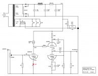
the schematic uses 470uF 350V, really is necessary so big or I can use a small film cap like 27uf or 10uF or less?
the capacity value have been covered well
but maybe it should be noticed that a big volume can size also have lower resistance(ESR)
a good film cap with that value is exstreme
if you have loads of money, you could order a large stack of Duelund caps
but maybe you can find a nice quality bipolar cap
or even a 'motor run' type cap might work well
I calculate with my old Casio fx-570 calculator.
See post 14, which you apparently used correctly in post 15. Or see any electronics textbook, or use Google - I told you the name of the circuit in post 13. Do you really want to be spoon-fed?
Ooops DF96 you are right
the capacity value have been covered well
but maybe it should be noticed that a big volume can size also have lower resistance(ESR)
a good film cap with that value is exstreme
if you have loads of money, you could order a large stack of Duelund caps
but maybe you can find a nice quality bipolar cap
or even a 'motor run' type cap might work well
Please read carefully all thread, I learned a lot with the kind people helping me to understand & calculate.
Please read carefully all thread, I learned a lot with the kind people helping me to understand & calculate.
yes, I noticed some changes
but maybe other members would build it, and still use the big lytic cap
also can improve changing the cathode caps & resistors with LEDs, if yes wich value 1.9-2.1V 20mA can be enough? there is other ways to improves the MJ design?
When you study the schematic carefully you will see that the first stage draws about 4mA and the second about 9mA... a string of two orange LED's did the trick when I built the MJ a couple years back. The entire conversion was guided by Morgan Jones himself back then
worship: ), and it worked perfectly. You need to bias the first stage to about 3 - 3.5V that's why I used two orange LED's. They can be rather generic since you are only dealing with 4mA current draw.
I was playing with the idea of the MJ with different tubes also (to have more current draw through the second stage) and came up with a schematic using russian 6N23P and 6N6P... but I actually never built it like that.
Using the SSHV2 is always a good idea since it is good to power pretty much anything
Attachments
May be better to build it as it is, then upgrade it later. A common mistake made by inexperienced folk is to want their first ever build to be so perfect that they will never need to change it. The result can be frustration for them and us, as it doesn't work but they can't tell us exactly what they have done - all we know is that it is different from the published circuit.merlin el mago said:To improve the design I will use SSHV2 shunt regulator + CCS, also can improve changing the cathode caps & resistors with LEDs, if yes wich value 1.9-2.1V 20mA can be enough? there is other ways to improves the MJ design?
If so don't learned nothing, diy is the way to learn & improve the devices.
perhaps, but how others choose to build it will their problem
no need for that attitude
looks like a fine design, and nicely improved
but not everyone knows how to handle/wire a ccs
they might want to build it without, and so on
and they may not want a huge and expencive poly cap
which it still is
why wouldn't a simpler and cheaper version be ok
could be its still a fine headamp, despite the better options
- Home
- Amplifiers
- Tubes / Valves
- The Morgan Jones mini tube headphone Amplifier