Hello! I was given this amplifer in payment for repairing a friends Ham Transceiver. I believe it was built about 1986 or so. Would anyone have a schematic for this amp? I believe Dick Smith may have sold it as a kit.
Another person tried to "repair" it by blanketly replaceing o/p and driver transistors which tested OK by me. They come in a we plastic bag.
I am hopeing to repair this vintage amplifier. Then modify it to improve the sound etc.
I have a Plinius 3 (1980) vintage amp that I have repaired (10 years ago) and recienty modified polyethylene caps, metal film resistors etc. It has two toroidal trannys.
Anyhow, I need another project to play with
Thanks guys.
Tony.
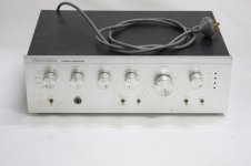
EA 60/60 Integrated Amplifier Kit.
Hi Tony
No schematic that falls to hand at the moment, sorry, but it is a common EA and SC circuit of that era using a standard Hitachi design that first appeared with the introduction of Mosfets for the LTP with CCS and "balanced" VAS using TOI26 BF469/70 transistors. It uses MJE340/50 drivers with an MJ15003/4 complementary pair EF output - all on a full-size PCB with a C-core transformer PSU for 50V rails. It's very good for the age, very low noise (<-100dB) but needs a matched input pair badly. Arguanbly, it's EA's best design in bangs/buck
Bias is "optimum" 25mV and the Vbe multiplier, sensor, if TO92, gave assembly trouble. A mod using a joggled TO126 in the same location was the EA solution.
They are one tough and reliable amp, easy to work on and the RIAA MM input is a ripper with very low noise 2SC2545 LTP and NE5534AN. My amps are still going strong with original Philips main Electrolytics and other standard parts.
Expect trouble with the input selector switch, volume control mounting, pushbutton switch contacts and the relay operation as it is interlocked with the headphone socket switch which may need a bit of work to get the relay to operate correctly and switch the speakers on. It's a fancy but poor socket/switch and is insulated from ground intentionally.
If the power transistors are toast, it has been really abused !
Hang in if no one else can find a copy - I may still find it
Thanks Ian finch!
You seem to know the amplifier well. I have been working on my Plinius 3. It has come up well.
I guess a "matched pair" would get the offset right (no DC at speaker terminals). My Plinius had blown o/p trannies, same type as the EA 60/60. I think people enjoy hooking as many speakers to there amp as possible. Me, I learnt that lesson years ago
Thanks for info about the idle current. My plinius I monified for DC offset. Installed a pot at one of the negitive feedback transistors supply. Was 50mV. Now is 0mV!
This made my left speaker happy!
Anyhow, thanks fellas, At least the amp doesn't use 2N3055, MJ2955. That was great news.
Also, diddn't know what the tranny was, "C" type. Cool, thanks!
I read about the "Cheep input switches" Least' me Plinius 3 doesnt have that problem (no bloody input switches! haha.
I am looking forward to getting the old girl going, she can live here elder years out in good hands. I found a circuit for the "Playmaster 40" dated 1976. has a bit in common.
The RIAA will come in handy with my (friends) old Technics record-player.
Guess the volume pot nut comes loose???
What the speaker relay do? Is it for the headphones? please explain if possible. I havent had the PCB out yet so...
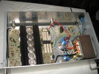
If the tranny is good, will mod for seperate diode bridges and filter caps (havent had a close look yet so I could be talking rubbish!) Should inprove stereo seperation.
Will test o/p and drivers for leakage (shorts etc) and prob replace emiter resistors. Once I have it going. May post here the results.
I would love a copy of the article from EA glennb! It should be on the net for everyone to download (love the net for this reason)
Let me kno if you need help with anything glennb, and Ian finch thanks for takeing the time to publish the alignment info etc.
You Aussies are great, really!
You seem to know the amplifier well. I have been working on my Plinius 3. It has come up well.
I guess a "matched pair" would get the offset right (no DC at speaker terminals). My Plinius had blown o/p trannies, same type as the EA 60/60. I think people enjoy hooking as many speakers to there amp as possible. Me, I learnt that lesson years ago
Thanks for info about the idle current. My plinius I monified for DC offset. Installed a pot at one of the negitive feedback transistors supply. Was 50mV. Now is 0mV!
This made my left speaker happy!
Anyhow, thanks fellas, At least the amp doesn't use 2N3055, MJ2955. That was great news.
Also, diddn't know what the tranny was, "C" type. Cool, thanks!
I read about the "Cheep input switches" Least' me Plinius 3 doesnt have that problem (no bloody input switches! haha.
I am looking forward to getting the old girl going, she can live here elder years out in good hands. I found a circuit for the "Playmaster 40" dated 1976. has a bit in common.
The RIAA will come in handy with my (friends) old Technics record-player.
Guess the volume pot nut comes loose???
What the speaker relay do? Is it for the headphones? please explain if possible. I havent had the PCB out yet so...
If the tranny is good, will mod for seperate diode bridges and filter caps (havent had a close look yet so I could be talking rubbish!) Should inprove stereo seperation.
Will test o/p and drivers for leakage (shorts etc) and prob replace emiter resistors. Once I have it going. May post here the results.
I would love a copy of the article from EA glennb! It should be on the net for everyone to download (love the net for this reason)
Let me kno if you need help with anything glennb, and Ian finch thanks for takeing the time to publish the alignment info etc.
You Aussies are great, really!
I would love a copy of the article from EA glennb! It should be on the net for everyone to download (love the net for this reason)
Let me kno if you need help with anything glennb, and Ian finch thanks for takeing the time to publish the alignment info etc.
You Aussies are great, really!
EA articles & errata have been scanned. Give me a day or so to crop and print to PDF and upload.
Thanks Glenn. Please take your time.
One thing that I have learnt tonight, regarding modifying for better quallity, is a pair of diodes installed before the voltage-dropper resistors that supply current to the pre-amp section. At least on my Plinius 3. With the Plinius I will add these "isolation diodes". Also a 100uF 25V electro to assist the 100nF Poly!
I see that when the o/p stage is drawing loads of current, the preamp will be happy.
Thanks guys.
Tony.
Hi Tony... I found a circuit for the "Playmaster 40" dated 1976. has a bit in common........Guess the volume pot nut comes loose???
What the speaker relay do? Is it for the headphones? please explain if possible.
First, my error - mV should be mA bias current ( I have very poor specs too!)
The 40-40 has some similarities but not the balanced VAS or faster transistors
The closer design is the 2002 SC480 module which has been posted here on a few threads. It uses cheapest parts with 2 pair 2N3055/2955 varieties for it's utility purpose, but the rest is pretty much similar design. It's amazing what a few modern, matched semis can do for sound quality in this circuit, which is not far removed from a basic Symasym.
The speaker relay cuts the speakers off in the event of DC on the outputs, as could happen with a serious amp. fault. One of the headphone socket switches also drops the relay out by breaking power ground to it when the headphones are plugged in. Other switches then feed output to the tip and ring contacts of the headphones via the usual dropping resistors.
This has the benefit of avoiding flimsy rotary speaker switches and usually redundant controls but unfortunately, the socket switches became erratic. So it wasn't unusual to think the amp was dead but a few uses of the socket returned normal operation. Problems with the LORLIN or ALPHA moulded selector switch and stress of the volume control soldering to the PCB also made a frustrating experience when all and sundry used the amplifier. That was a case design issue as much as anything else.
Anyway, the schematic and description in the article(s) will clarify precise detail, but I have heard of people trying to repair this by fixing the amp. Well it wasn't broke - they just didn't understand the relay operation or what bad solder joints and oxidised contacts do.
It's hard to blow these as the small, perhaps 150VA transformer, sags the power supply and limits current into normal loads. Give it stiff supplies and I guess you would toast those mighty outputs like any silicon. It will pump 90WRMS, single channel, so it does have output and headroom well above it's nominal rating.
Last edited:
Thanks Ian Finch. I guess the o/p trannys are raded for 20 amps. Ine can solder at I think 285 degrees for 10 secs. The fuse might be 2 to 3 amps or so!. Your explination was the same as my conclusion! The person tried to fix the o/p when there was nothing wrong with it. The original trannys (Motorola) are dated 8631 (31st week of 1986). New ones are from memory 2004. This would have been when my friend received the amp. Haha, I guess he did a good job, for a novice! "Replace the biggest high power parts first" trick.
Well, it is amazing what one can conclude by just looking and seeing what was done. One can work out a probable cause or reason for falure.
Thanks for all the help. I researched the "C" tranny. Looks promising. Wish I had a second one!! To mod to dual tranny. Anyhow, there is no reason why an old amp cant sound magic after replaceing all the parts! Change carbon to film resistors. Remove all ceramic, replace with film caps, pref polyethylene or better Polystyrene. Beef up wiring to o/p. Heat sink bridge rectifier/s. etc.
Had my fair share of relay problems in ham radios. Strip of wet and dry sandpaper to the rescue!
Tony.
EA articles & errata have been scanned. Give me a day or so to crop and print to PDF and upload.
http://dl.dropbox.com/u/44941643/Playmaster-60-60-v2.pdf
4.61 MB, 19 pages, scanned at 150 DPI, 256 greyscale
Copyright Federal Publishing 1986-1987
Reproduced for the purposes of fair research non-commercial use
Excellent work, thanks glennb.EA articles & errata have been scanned.
Let me know if you would like scans of other EA Playmaster amplifiers or articles for personal research purposes. Sorry, I don't have ETI or SC.Excellent work, thanks glennb.
I scanned the 1989-1990 EA Pro Series One power amp a couple of years ago. 140W 0.007% THD using 2 pairs of 2SJ49 / 2SK134 MOSFETs. I built my own PCB version of this in the 1990's as 3 channels (L,R,SW) in a 3U rack case. Anyone interested in a link to the PDF?
Thanks for that! I appreciate your time involved with scanning and providing me with much wanted info! Offer remains, if you need anything... just ask, I'll see if I can be of assistance. Merry Xmas to all on this forum.
Think I will modify the relay to the job of speaker-dethumpin'. I will have a go at repairing the old girl soon. Will post results here. Could add up to be a laugh fellas!
Cheers, Tony.
Think I will modify the relay to the job of speaker-dethumpin'. I will have a go at repairing the old girl soon. Will post results here. Could add up to be a laugh fellas!
Cheers, Tony.
Thank you for this PDF-URL.http://dl.dropbox.com/u/44941643/Playmaster-60-60-v2.pdf
4.61 MB, 19 pages, scanned at 150 DPI, 256 greyscale
Copyright Federal Publishing 1986-1987
Reproduced for the purposes of fair research non-commercial use
The brand name "Playmaster" I have never heard before
Playmaster amp build or not
Playmaster Stereo Amplifier - ALLBIDS Auction 480065
My Playmaster series 200 integrated amp. 100W / channel into 8 ohms mosfet. - My Photo Gallery
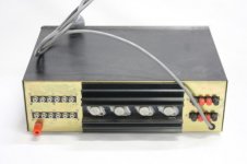
Who knows the model of the amp from the first both attached images?
BTW - I am looking for world's best vintage magazines - go to
http://www.diyaudio.com/forums/soli...ble-electr-audio-magazines-2.html#post2854966
If you know some other there already not mentioned ones, please post it there - thank you
Attachments
Last edited:
Hi Tiefbassuebertr.
For your opening question, Playmaster was the title of audio kits designed by staff of Electronics Australia magazine from around 1950 when it was known as Radio & Hobbies magazine to its closure in 2006 IIRC. They were quite numerous in homes during the peak electronics age of 1970-1980, some models sold in 10s of thousands quantitities.
The tradition is continued with some EA staff now working for Silicon Chip magazine, also here in Oz.
Though the artwork differs from mine, I believe the amplifier is the 50W Mosfet amplifier from 1979. Naturally, it used a single pair Hitachi 2SK134/J48 and a even the Hitachi circuit. Not good sounding, unfortunately.
Last edited:
Hi Tiefbassuebertr.
For your opening question, Playmaster was the title of audio kits designed by staff of Electronics Australia magazine from around 1950 when it was known as Radio & Hobbies magazine to its closure in 2006 IIRC. They were quite numerous in homes during the peak electronics age of 1970-1980, some models sold in 10s of thousands quantitities.
The tradition is continued with some EA staff now working for Silicon Chip magazine, also here in Oz.
Thank you very much for sending this informations. Do you know, whether there is online a "Master TOC" from all exist "EA" magazines ?
Most amplifier that I know with Hitachi 2SK134/J48 don't sound good (both commercial and diy versions) if they work with idle currents through the output pair below 200mA - independend of the front end topology.Hi Tiefbassuebertr.
Though the artwork differs from mine, I believe the amplifier is the 50W Mosfet amplifier from 1979. Naturally, it used a single pair Hitachi 2SK134/J48 and a even the Hitachi circuit. Not good sounding, unfortunately.
Last edited:
That would be good, but I don't believe there is such a list. Annual lists were published in the magazine, yet maybe only 2 amplifiers were published annually, so research is difficult.
SC magazine, have compiled a DVD archive of the magazine, complete from 1939 to 1965 but this misses a period of greater interest. They do have back numbers but a reasonable fee is charged for duplicates of any article. There may be a website archive so I will look and also email the editor of SC. I'll post here if anything turns up in the next week or so.
SC magazine, have compiled a DVD archive of the magazine, complete from 1939 to 1965 but this misses a period of greater interest. They do have back numbers but a reasonable fee is charged for duplicates of any article. There may be a website archive so I will look and also email the editor of SC. I'll post here if anything turns up in the next week or so.
Last edited:
http://dl.dropbox.com/u/44941643/Playmaster-60-60-v2.pdf
4.61 MB, 19 pages, scanned at 150 DPI, 256 greyscale
Copyright Federal Publishing 1986-1987
Reproduced for the purposes of fair research non-commercial use
dear,
where is pcb .
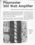
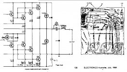
PLayMaster Amplifier Electronics Australia, June 1980
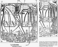
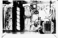
Real heavy duty Amplifier,Playmaster 320 watts amplifier published in Electronics Australia, June 1980 . I made 6 of these amplifiers in 1988 and using them till date. for my programmes,using 6 of these amps I could provide sound for gatherings of 15,000 people, i am using 2n3773 version with 12 transistors in each channel,70-0-79 D.C. rail voltage.never failed me.attached are photos
Real heavy duty Amplifier,Playmaster 320 watts amplifier published in Electronics Australia, June 1980 . I made 6 of these amplifiers in 1988 and using them till date. for my programmes,using 6 of these amps I could provide sound for gatherings of 15,000 people, i am using 2n3773 version with 12 transistors in each channel,70-0-79 D.C. rail voltage.never failed me.attached are photos
Attachments
- Status
- This old topic is closed. If you want to reopen this topic, contact a moderator using the "Report Post" button.
- Home
- Amplifiers
- Solid State
- Playmaster Sixty-Sixty Stereo Amplifier SCHEMATIC