That's correct.
I'm planning to implement something quite similar to that. Would Akabak model the effects of such bracing?
Making up a shear web using 5.2 or 6mm veneer core plywood, and 3/4x3/4 in stock would be lightweight, and perhaps be so small in cross-section that it didn't need to be accounted for.
An externally hosted image should be here but it was not working when we last tested it.
I'm working on a sheet to handle the design side of the equation.
I'm trying to do everything at the cell level, and have hit a snag. I am using a simple factor to correct for the path length variation due to the mouth. I would like to make it a little better, but am hitting a circular logic problem.
This is what needs to be worked out.
L=((34300/15.21429)/4)=563.615
Mo=10000*((388.3156/10000)*((COSH((Lc/100)/3.5774183)+(.51*SINH((Lc/100)/3.5774183))))^2)
Q=((SQRT((Mo/PI())))*2)*.6
Lc=L-Q
I think I have been looking at it too long.
Attachments
Much more math intensive/complete than my meager 'cheat sheet', but at a glance looks good for getting a neophyte started, though I'm curious why you used a 343 m/s SoS rather than HR's 344 m/s, not that I believe it audibly alters a design.
Anyway, thanks for the effort!
GM
Anyway, thanks for the effort!
GM
GM,
Thanks for the words.
The 343m/s is just a "me" thing. I have always had an easier time getting my calculations to work when using it. Kinda of a good luck thing. My personal calculations were all for AkAbak, and I used 343 there.
When comparing the hyperbolic horn from the math with HR it pulls up the horn cut off ~.1Hz higher, so it isn't a killer here, and the front and rear chambers come in with a 1% difference. Close enough to keep my luck going!
If you, or anyone else notices anything off please let me know.
If you, or anyone else notices anything off please let me know.
Hi soho54,
Using the following test input parameter values I get L34 = -17.88 cm for a 3-segment tapped horn:
Fs = 50 hertz
Qes = 1
Qms = 1
Vas = 50 litres
# Drivers = 1
m = 0.5
Low corner = 34 hertz
High corner = 59 hertz
(The values of the other driver input parameters do not affect this result).
Kind regards,
David
Thanks for the reply.Hi soho54,d
This is something I should have automated in case it ever popped up.
The rear tap position is actually set from the horns throat. With the correct parameters you end up with a horn whose physical path length is less than the needed rear tap position when the end/mouth correction is added in. In this case the calculated Rear Tap is beyond the end of the physical horn, and is indicated by a negative value.
With a TH...
Enter everything in, and input the negative number as ".1" Now when you enter the Wizard with the Horn-S2 Variable on, increase the last segment until it equals L12, so the tap will be at the very end of the horn. The horn end will be a little off though this way.
With an Nd/OD...
Enter everything in, and input the negative number as ".1" The negatives in the Rear chamber just means it will be impossible to exactly hit the requested corners in the present horn. Reactance annulment the Leach way is out.
This is the first thing on the list to add next time. Some of the extra parameters are not used right now, but were in the past, and will be in the future. I think I may redo the front to remove them for the time being as well.
Last edited:
Any updates to the Stepped TH sheet?
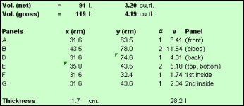
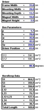
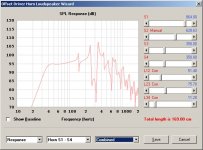
Here's a quick update - an additional sheet that can be used to model the layout of a mass-loaded TL (the port is a shelf vent at the end of the line, and it's modelled as an offset horn in HornResp).
This one's a bit easier to use than the stepped TH sheet (considering that there's a lot less folds!). The approach is a bit different as well, as you basically enter the box's physical characteristics, and the HornResp data is calculated. You can of course use the Goal Seek tools if you want to start with existing HornResp data and try to create box to match.
To use the spreadsheet:
1. Enter the driver's dimensions
2. Enter the box dimensions, and the position of the driver on the front panel (measured from its center)
3. use the goal seek tool to adjust theta so that S12' matches S12
The approximate HornResp data to model the enclosure will now be given in the HornResp Data section.
This is v0.01, so any suggestions for corrections or updates will be welcomed
Attachments
I will look carefully at it Brian.
Thanks for your efforts. A lot of work went into this for sure.
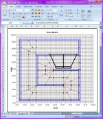
Thanks Mark. I think I have most of the bugs worked out. And after all that work, it looks like the first alignment I wanted to try with it won't work, LOL. I can't place the driver in the location it should be for the best response, according to HornResp. And if the driver is not in the optimum location, a discontinuity appears the passband. I might go ahead and try it anyway, just to see if (1) the discontinuity appears, (2) if it's as big as HornResp suggests, and (3) if it can be reduced or eliminated with a bit of stuffing near the big end of the "line".
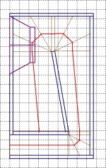
See images below for more info:
Attachments

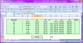
The length for the back side in the cut sheet is wrong.
Notices it after wood was cut though
Should obviously noticed that it was not the same length as the sides.
*edit* for the stepped TH
Hmm...
Looking at my copy, it looks like the "x" and "y" measurements are reversed in the cut sheet table.
Rotating the back side by 90 degrees before attaching it to the other panels should be a quick fix.
I'll update the spreadsheet.
Nope, rotating won't work.
X and Y are the correct axis, It's just that X is too short.
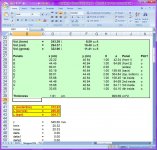
Shouldn't the value be calculated from AC19-AB19 instead of AB18-AB19?
Seems to fit.
Or just use value of height (D16)
Hmm... the back panel should have the height of the side panels, and the width of the internal panels. What's your cut table in the spreadsheet look like?
If you open the boxplan in post #91 and change the depth to 100 the back panel also change to 100. But it should stay at 56,7 as the height has not changed.
I finally got a chance to look at this. Yep, it seems like an error. The height of the back panel was being calculated incorrectly. I did a quick fix (see attached), but came across another minor issue - when you enter dimensions, they're used as external dimensions rather than internal ones (so the external dimensions will be larger in each direction by 2*panel thickness).
I've decided to rewrite that section of the workbook anyway, and will upload the complete version when finished (a few weeks, as I'm converting it from a stepped to a continously expanding horn, and including some calculations for bracing).
Attachments
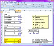
I know I'm being anal, but why is this TQWP not 825.8cm2 (16" x 8") thru the whole 304.80cm (10ft) pipe? Under Initial Parameters, h should = 81.28cm (8" x 4 x 2.54cm). Are those parameters internal or external?
Attachments
- Home
- Loudspeakers
- Subwoofers
- Spreadsheet for Folded Horn Layouts...