Mouser Catalog, look at the label on the side of the page, your looking for "Rectangular Connectors" At top of page look for "3M .100" x .100" Pin Strip Header" Mouser part no. 517-6111tg 40 pin straight, just cut to length. The female part I use is the CHG -2020 "3m headers & wire housings". It's a double row socket that you punch down the wiring into then with a small screw driver fold over two metal tabs to retain the wire (I'm sure their is some special tool for this). Look for the CHG series the CHG 10 series are single row, and the 20 series are double row.Well, maybe so. I looked up the parts kindly mentioned by 1audio but they didn't seem right to me. I went digging through the Mouser catalog and I'm still not sure if I found the right part. There's a lot of things I don't know. I guess sometimes solder solves the unknown just as good.
I just received my rack mount chassis from Par-metal. Wow! This is far far better than the Hammond box I bought before. The quality of the series 14 is outstanding! They are getting all of my business from now on.
Also, since Victor didn't supply a template for a face plate for his oscillators, and the fact that I'd more than likely NOT get the holes in the right place, I'm going to modify his board. I'm going to take off the pot, the LED, and the two RCA jacks and use different ones directly on the front panel and wired to the board remotely.
Also, since Victor didn't supply a template for a face plate for his oscillators, and the fact that I'd more than likely NOT get the holes in the right place, I'm going to modify his board. I'm going to take off the pot, the LED, and the two RCA jacks and use different ones directly on the front panel and wired to the board remotely.
Template is on his eBay listing. However, your idea gives a lot of flexibility.
Yeah, I have difficulty doing layout to 0.5mm. I didn't see that before obviously.
Speaking of which, what would be the best way to provide a balanced output for this oscillator? Galvanic isolation is also desirable, so I'd have to use a transformer for that. I'm going to try out the mixed feedback method as described by Lundahl:
http://www.lundahl.se/pdf/ovrigt/feedbck.pdf
Walt Jung got good results using this method, as described in his op amp book.
Balanced output simply requires equal impedances to ground. It does not require signal balance to ground, such as a center-tapped xfmr. If you feed the oscillator with a transformer isolated power supply and do not bond the common, you have a balanced output. It is floating, but balanced nontheless. I then wire a + and - terminal for signal (floating/balanced) and then a grounded shield wire.
All that is suggested then is whatever you are driving be a differential input with equal resistances to ground for a DC reference. I rarely have good noise results with a floating system; it should be grounded somewhere. Just make sure this ground reference provides equal impedance to ground, and that the shield is grounded in at least one spot (ideally the input side in this case, near where the reference bond exists).
This is somewhat backwards from the ideal condition, where the source is referenced, and the shield grounded at the source. But careful layout and wiring can result in the 'backward' style being just as noise free.
Does the quality of the potentiometer matter for Victor's oscillator? I managed to get it out, but what ever solder he used is really difficult to work with. It won't come off very well with solder wick and I don't have a suction bulb handy. I don't like this solder at all. It's a pain in the @ss basically. Anyway, the pot is a really cheap carbon 10k. I wonder if a better pot would improve anything? Lower noise maybe?
Does the quality of the potentiometer matter for Victor's oscillator?
A true audiophile never stops thinking that anything must matter, eh?
")
As seen in the schematic (http://www.diyaudio.com/forums/equi...distortion-audio-range-oscillator-27.html#265) the pot simply controls a DC voltage which forms the amplitude reference for the leveling loop. The sinewave does not pass through it, so there's little point replacing this part.
Samuel
A true audiophile never stops thinking that anything must matter, eh?
As seen in the schematic (http://www.diyaudio.com/forums/equi...distortion-audio-range-oscillator-27.html#265) the pot simply controls a DC voltage which forms the amplitude reference for the leveling loop. The sinewave does not pass through it, so there's little point replacing this part.
Samuel
HAHAHA, yeah, you're right.
Thanks for the information.
but what ever solder he used is really difficult to work with. It won't come off very well with solder wick and I don't have a suction bulb handy.
I have found on difficult solder that I get good results if I pre-wet my wick with flux. Even if the wick already has flux in it (the flux dries out).
I have found on difficult solder that I get good results if I pre-wet my wick with flux. Even if the wick already has flux in it (the flux dries out).
OK. I don't have any flux so I suffered through a painful removal of some parts off of his board. What a mess! I guess I'd better go buy some. I was using Chem-wick, but it may be old.
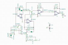
I put Victor's oscillator into Tina just in case I need to make one myself. I'm not sure it's oscillating. I looked up the parts he's using and used something else that's similar, like a high gain PNP transistor BC560C, and the J111 jfet. I don't really understand this circuit, so I am unable to fine tune it. Any help is appreciated.
Attachments
I put Victor's oscillator into Tina just in case I need to make one myself. I'm not sure it's oscillating. I looked up the parts he's using and used something else that's similar, like a high gain PNP transistor BC560C, and the J111 jfet. I don't really understand this circuit, so I am unable to fine tune it. Any help is appreciated.
If you know how to install parts into LTspice I can send you Jfet models.
I don't use Tina so I can comment on that.
Your loop gain is too low.
David.
If you know how to install parts into LTspice I can send you Jfet models.
I don't use Tina so I can comment on that.
Your loop gain is too low.
David.
Hmmm, thanks. I did notice that I had the power supply set to +/-5V, so I changed that. The J111 jfet is supposed to be the same as the one Victor used. I also copied all of his resistor and capacitor values. How do I increase the loop gain?
I put Victor's oscillator into Tina just in case I need to make one myself. I'm not sure it's oscillating. I looked up the parts he's using and used something else that's similar, like a high gain PNP transistor BC560C, and the J111 jfet. I don't really understand this circuit, so I am unable to fine tune it. Any help is appreciated.
Dirk,
1) I see two mistakes in schematic:
R17 must be 120k.
R10 must be 10k + 100ohm.
2) Settling time after swich on is tens of seconds. Simulator must be configured for this, if it possible.
3) Power supply voltage must be +/-15V. With lower voltage, you may not drive JFET properly.
Hmmm, thanks. I did notice that I had the power supply set to +/-5V, so I changed that. The J111 jfet is supposed to be the same as the one Victor used. I also copied all of his resistor and capacitor values. How do I increase the loop gain?
The RDs on matches and that about it.
The Idss is much higher and the capacitance is lower for the 4391.
I'm not sure the the gate is ceter on the j111 as it is with the 4391.
I have the model if you want it.
You can try decreasing R7's value. It's tight for gain adjustment with this oscillator.
Any attempt to increase gain at the output drive will upset the filter.
David.
Dirk,
1) I see two mistakes in schematic:
R17 must be 120k.
R10 must be 10k + 100ohm.
2) Settling time after swich on is tens of seconds. Simulator must be configured for this, if it possible.
3) Power supply voltage must be +/-15V. With lower voltage, you may not drive JFET properly.
Thanks!
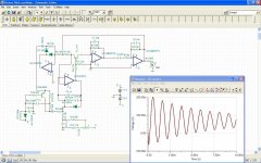
I have trouble using my software to look at this circuit. I tried the software 'scope but didn't see any output. Since it doesn't have a signal source, I'm at a loss right now to figure out if it's working correctly.
The RDs on matches and that about it.
The Idss is much higher and the capacitance is lower for the 4391.
I'm not sure the the gate is ceter on the j111 as it is with the 4391.
I have the model if you want it.
You can try decreasing R7's value. It's tight for gain adjustment with this oscillator.
Any attempt to increase gain at the output drive will upset the filter.
David.
Thanks for your help.
I'm getting basically no voltage across the jfet. I can't figure out why. There's a tiny negative DC voltage from drain to source, and the gate is at 170mV or thereabouts.
I just need the *.lib file for the jfet, thanks.
Attachments
You'll have to run a transient analysis for a long time.
When simulating oscillators, I use a current source to inject a few cycles right at start up. this can get it running a lot quicker.
Ah! so that's what I do.
Ok, tried that. I got a really ugly looking oscillation. I ran it for both 10 and 20 seconds. Sump'in ain't right.
- Home
- Design & Build
- Equipment & Tools
- Low-distortion Audio-range Oscillator