[...]The current sources are not in the signal path and can be made to not contribute noise (heavy degeneration)[...]
As I understand it, a BJT current source can be degenerated with high value emitter resistors. Correct?
May I ask how this can be done with a JFet current source? Can a depletion mode current source count as degenerated if used below IDSS (i.e. with source resistor)?
There is another way
I was refering to Dick's circuit. But that set of trims you show might be a little difficult in practice.
Attachments
As I understand it, a BJT current source can be degenerated with high value emitter resistors. Correct?
May I ask how this can be done with a JFet current source? Can a depletion mode current source count as degenerated if used below IDSS (i.e. with source resistor)?
Yes, but a different set of equations. If the degeneration resistor is significantly more than the 1/gm there is a benefit.
Thanks. If I understand correctly, that would lead, with real world parts, to JFET ccs who require quite a big headroom to operate, or the use of not so ideal JFET's for a ccs (short channel).Yes, but a different set of equations. If the degeneration resistor is significantly more than the 1/gm there is a benefit.
Thanks. If I understand correctly, that would lead, with real world parts, to JFET ccs who require quite a big headroom to operate, or the use of not so ideal JFET's for a ccs (short channel).
Yes, you have to spend volts. However, you have the advantage of practically no gate current noise, compared to the at-least shot noise in the bipolar's base current. The voltage noise of the two devices will be a noise source to figure in (which ties into Scott's remark about the benefits coming in when the external R is larger than 1/gm).
A hybrid of bipolar and JFET, as shown probably first by Jaeger, can give very high output impedance and good noise performance. The depletion-mode FETs gate is tied back to the bipolar emitter and resistor junction. With bipolar gm so high typically, most of the gate current due to the drain-gate capacitance, for a typical circuit, flows in the emitter. The result is a very low output capacitance until high-frequency effects begin to spoil it.
Another advantage of the JFET as current source comes from operation at the zero-tempco point, about which see the post of mine with the page from Cobbold's book. That current can be used to develop a voltage which is readily filtered and typically lower noise than most available voltage references, although it must be buffered for most such applications.
To add some color --- noise of a zener drops dramatically below the zeroTC voltage... something like below 4.7v. A 3.3 v zener for example will have a sudden drop in noise compared to higher voltage zeners. I often see higher volt zeners used in PS, for example. -RNM
Good point. Yes, I discovered that noise dependence myself at one point and was a little unhappy about it
") It's as if the diode can't decide if it wants zener action or avalanche behavior Nonetheless I fine-tuned samples for minimum tempco and used them in one-off subsystems.
It's as if the diode can't decide if it wants zener action or avalanche behavior Nonetheless I fine-tuned samples for minimum tempco and used them in one-off subsystems.SY reports that red LEDs are quite quiet, but they do have a large net temperature coefficient when you put them in series to get reasonable voltages. Individually they are a pretty decent match to bipolar Vbe tempcos, although not something that one would rely upon in precision apps.
That what this Pioneer patent is said to address
US4356453.html
"Accordingly, an object of this invention is to provide a grounded-source type field-effect transistor circuit in which the source resistance is minimized to minimize the thermal noise in the circuit and to increase the circuit gain."
Adds more devices though.
rgds
james
Patents can be tricky things -- a current source where before there was a resistor and a jFET where there was a bipolar. Small things sometimes but in a competitive market it can help. For me it is the concept that counts - but knowing that the results are in the details.
I published the same bias topology with an all bipolar compl-push-pull line stage in the quarterly, TAA (3/80).
[The work, of course was done long before it got around to publishing.]
Pioneer never called me when I published my circuit maybe because it would put their patent in question as obvious appl of existing design. Note: Pioneer applied for thier patent same year (1980). And, granted in 1982. Certainly the circuit details are different (allowing a patent) but the bias topology had been done before their patent.
PS -- many of you know that when you work for a university or government - all inventions belong to them. One invention was a circuit topology for a MC pre-preamp appl. I got release from the Lab's patent lawyers to patent it myself... it had no use to their work so didnt want to pay for the patent -- I published it instead. What do I need a patent for that i should spend 10 grand to get it? And, I liked my day job. - Dick Marsh
Last edited:
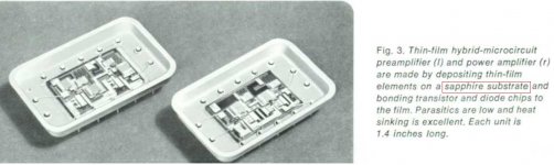
In 1970'th we made power amps on beryllium ceramic.
The thermal model requires DC stability, DC identical, and a way to fast couple devices which should be tracking one another. You're two examples were incongruent as you they had different dissipation ratio's
jn
I still can’t grasp it (don’t worry jneutron, it’s not your fault), but I found an extreme implementation –pages 9 to 11 of the link- that proves me wrong.
And like I promised, now I’ll shut my mouth (but the earth rotates…
)http://www.hpl.hp.com/hpjournal/pdfs/IssuePDFs/1971-01.pdf
It is exactly what Wavebourn initially suggested.
George
In 1970'th we made power amps on beryllium ceramic.
Who is “we”?
George
Who is “we”?
Soviet NIIPP, i.e. Tomsk Institute of Semiconductor Devices. It was a scientific institute with own manufacturing base. Our division was called Laboratory of Thick ICs. It is known by so called "Kremlin Pills", devices that were swallowed to restore intestine peristaltic.
Last edited:
Good point. Yes, I discovered that noise dependence myself at one point and was a little unhappy about it
SY reports that red LEDs are quite quiet, but they do have a large net temperature coefficient when you put them in series to get reasonable voltages. Individually they are a pretty decent match to bipolar Vbe tempcos, although not something that one would rely upon in precision apps.
So I wonder -- do some bipolars (or jFETs) have a similar sudden noise drop when operated at low enough voltage threshold?
So I wonder -- do some bipolars (or jFETs) have a similar sudden noise drop when operated at low enough voltage threshold?
I've never seen it observed by anyone in the literature. With zeners we are talking a horrible excess noise mechanism that goes away at lower breakdown , but the noise never gets below the thermal noise of the series resistance. With transistors the noise can be computed from the physics and some basic principle would have to be violated to observe less noise.
I still can’t grasp it (don’t worry jneutron, it’s not your fault), but I found an extreme implementation –pages 9 to 11 of the link- that proves me wrong.
And like I promised, now I’ll shut my mouth (but the earth rotates…
http://www.hpl.hp.com/hpjournal/pdfs/IssuePDFs/1971-01.pdf
It is exactly what Wavebourn initially suggested.
George
Thank you for that nice link. Thier "bootstrapping" of the drain/source leads is a somewhat rudimentary design. We call it a thermal "anchor", or "heat station" here, but we do it to a 4.5 kelvin LH2 point, or a 50 Kelvin LN2 point. We need to measure to accuracies of .001 Kelvin in the 1.88 to 55 Kelvin range.
A better design would use 4 serpentine runs on the substrate, and there would be symmetry in the lengths of the drain and source wires. Otherwise, there could be a forced gradient across the chip drain-source channel. Oh, we also use #32 AWG phosphor bronze wire to reduce along the wire conduction.
jn
Oh, we also use #32 AWG phosphor bronze wire to reduce along the wire conduction.
jn
I understand that is a necessity at your activities to split hairs, not common to others jobs.
I have noticed the effect of wires heat conduction and/or added heat inertia in more down to earth applications with this hobby . For wiring thermal tracking transistors /bias adjustment in amplifiers and semiconductor temperature sensors,apart from cutting their leads short, I use very thin magnet wire (and as a bonus, added flexing and tight twisting).
George
A better design would use 4 serpentine runs on the substrate, and there would be symmetry in the lengths of the drain and source wires. Otherwise, there could be a forced gradient across the chip drain-source channel. Oh, we also use #32 AWG phosphor bronze wire to reduce along the wire conduction.
jn
I discovered the hard way that aluminum wire to gold plated Kovar has a residual 2-3uV/C thermocouple potential.
When I was about to resign from UCLA circa 1984, I did a preamp for InSb photodiodes of a fairly conventional sort (instead of what I wanted to do, which was one of the reasons to quit) and the coolant was liquid nitrogen. The dual transistors for each detector and silicon lens assembly were mounted on fiberglass standoffs, with the thermal conductivity adjusted to allow the JFETs to warm up to about 100 K. 77 K is far too cold for good performance with silicon JFETs.I understand that is a necessity at your activities to split hairs, not common to others jobs.
I have noticed the effect of wires heat conduction and/or added heat inertia in more down to earth applications with this hobby . For wiring thermal tracking transistors /bias adjustment in amplifiers and semiconductor temperature sensors,apart from cutting their leads short, I use very thin magnet wire (and as a bonus, added flexing and tight twisting).
George
- Home
- Source & Line
- Analog Line Level
- Discrete Opamp Open Design