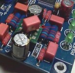
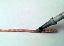
Just a little warning where it applies. The quality of sound had dropped significantly today. With some fiddling and prodding, I found one lead on the cap attached to the Brown Dog adapter had come loose. Re-soldered both leads and the problem was solved.
So I'm just suggesting for those who are moving the DAC around a lot, remember that's a vulnerable spot due to the small solder area involved.")
So I'm just suggesting for those who are moving the DAC around a lot, remember that's a vulnerable spot due to the small solder area involved.
Attachments
JLH Ripple Eater instead of Salas?
Have been following this thread with avid interest and am raring to get hands on on this DAC. Unfortunately it is not shipped to India so am making arrangements with friends in the US to do the ordering for me and have someone carry it to Mumbai. Hoping that it works out.
Has any one considered using the JLH Ripple Eater with this circuit. John Linsley Hood Ripple Eater - diyAudio
Compared to the Salas circuit it seems to be a lot more simple and, therefore, a lot more compact to build and include in a cabinet with the DAC. Comments on it eagerly awaited. Especially about the electrolytics recommended.
Got to thank all you guys for the amazing amount of info you have so willingly and selflessly shared on the thread. Great work! I am sure I speak for many when I say it is of immense help to all of us less technically inclined folk, and that it is greatly appreciated.
Have just purchased the AK4396 DAC in fully assembled form including a nice looking box and transformer from the usual place. One question, I have just ordered the parts from Claves bom and am wondering wht values R23, 24, 26, 28, 29, 30, 32, 34 should be?
On the bom it says the originals are a 2.4k but then it says to use PRP 2.2k's and then looking at the RS partnumber it points to 2.4k again? Can I use 2.2k's as this is what I have ordered? or is 2.4k preferable?
Regards
Simon
On the bom it says the originals are a 2.4k but then it says to use PRP 2.2k's and then looking at the RS partnumber it points to 2.4k again? Can I use 2.2k's as this is what I have ordered? or is 2.4k preferable?
Regards
Simon
I have just ordered the parts from Claves bom and am wondering wht values R23, 24, 26, 28, 29, 30, 32, 34 should be?
The right value is 2.4K.
PRP are indicated as 2.2K since the right value is not available.
Has any one considered using the JLH Ripple Eater with this circuit. John Linsley Hood Ripple Eater - diyAudio
Compared to the Salas circuit it seems to be a lot more simple and...
Erin, who started this thread, put a ripple eater together. but, it was for another project. don't know if he/she has tried the shunt, but may be able to give an opinion
http://www.diyaudio.com/forums/digital-source/189587-squeezebox-dac-vs-pc-dac-audio-quality-4.html
maybe send pm?
Last edited:
Sorry if I created the wrong impression that I have tried out the circuit. I've been toying with the idea of incorporating it in my PGA2310A based preamp but, to date, intention has not fructified to practise. I just wanted to know if anyone else had had the same idea of trying it out with the DAC and how it would compare with the other shunt circuits discussed on this thread.
Btw, I tried to attach a pdf file containing details of the Ripple Eater with my previous post but did not succeed. I will try to attach a smaller word document with this post and hope that it works.
Btw, I tried to attach a pdf file containing details of the Ripple Eater with my previous post but did not succeed. I will try to attach a smaller word document with this post and hope that it works.
Attachments
Just a little warning where it applies. The quality of sound had dropped significantly today. With some fiddling and prodding, I found one lead on the cap attached to the Brown Dog adapter had come loose. Re-soldered both leads and the problem was solved.
So I'm just suggesting for those who are moving the DAC around a lot, remember that's a vulnerable spot due to the small solder area involved.
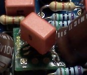
Hi, I've just fitted the cap to the browndog and I think I've noticed an increase in bass.
Would this be the case as the mod was first suggested to tighten the bass.
Is there a correct way round for fitting.
Last edited:
I didn't try alternate orientations but I suspect Dario may have.
No, I didn't...
But after the FE experience I can say mine is wrong...
Attachments
No, I didn't...
But after the FE experience I can say mine is wrong...
Hi Dario, could you please expand on your answer regarding the FE episode, I must have missed it.
Hi J,
I not only heard better bass, but the entire sound becomes fuller. More "liquid" as opposed dry and a little scratchy. I didn't try alternate orientations but I suspect Dario may have. Sounds like we are hearing the same improvements.
Hi Bob, yes things became fuller and a pretty good improvement.
I am now totally happy with my system and am rediscovering my CD collection.
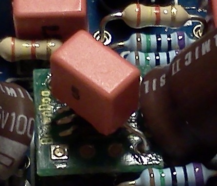
I haven't completed all the mods on the board, Not done large caps or the 4 resistors around the browndog as I am getting extremely nervous about ruining the board with too much soldering. I have particular difficulty with the resistors.
The FE episode was a series of auditions in an attempt to determine what differences could be heard by swapping the orientation of caps and resistors (mostly Caddocks) as they stand on the PCB. There was also some caparisons of brands and values. It was what generally goes on during a beta phase. My involvement started around here and here if you want the backgroung. I was a non believer before this process, but the orientation proved to be truly significant in dialing in the best sound.
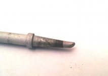
My best method - still not having a de-soldering station - is to use copper braid with lots of liquid flux to soak up as much solder as possible. It is important to let the braid heat fully and slowly draw it across the pad/lead end. Be careful to not pull the braid off if it has cooled. It will take the pad with it. Just reheat till you see it start sliding again. With some practice, parts need very little heat for final removal.
My best method - still not having a de-soldering station - is to use copper braid with lots of liquid flux to soak up as much solder as possible. It is important to let the braid heat fully and slowly draw it across the pad/lead end. Be careful to not pull the braid off if it has cooled. It will take the pad with it. Just reheat till you see it start sliding again. With some practice, parts need very little heat for final removal.
Attachments
Last edited:
I just received the power supply for my board and so far everything works great, thanks to all your helpful posts.
I, however, have a newbie question related to internal wiring. When I receive the case for my DAC, I consider using 2.5mm² OFC speaker wire for the PCB S/PDIF to RCA plug wiring. Is that a bad idea? I know the wire is supposed to be 75 ohms, but I'm thinking that a few inches of short, thick copper wire would pretty much equal soldering the plug right to the PCB. Am I being an idiot?
From the RCA plug to my source I have a proper 75 ohm digital cable, of course. I also have some coaxial antenna cable lying around, and of course the possibility of stripping a finished cable, although that is what I'm trying to avoid.
Last edited:
Please use EVERYWHERE the correct cable (impedance). There is NO gain in using 2,5 mm2 cable. The impedance is. If the impedance does not match, you will get reflections in the cable, and because of that bad blocks of data, which will degrade the signal.
Use proper 75 ohm cable (a video cable with RCA jacks is fine). For example: Farnell number 3711869. Hirschmann 724 is also a good idea.
So do not use the 2,5 mm2. It will not give you any benefit, but it will make even worse. The best result are obtained by the 75 ohm coaxial cable.
Use proper 75 ohm cable (a video cable with RCA jacks is fine). For example: Farnell number 3711869. Hirschmann 724 is also a good idea.
So do not use the 2,5 mm2. It will not give you any benefit, but it will make even worse. The best result are obtained by the 75 ohm coaxial cable.
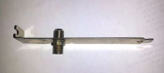
What about using one of these on the DAC chassis?
27025 Amphenol RF | Mouser
5-1814823-1 TE Connectivity | Mouser
Don't know if the spdif ground needs to be isolated from the chassis ground? Even if thats the case, isolation washers like those used for chassis mount RCAs could be used. The same piece can be wired to the motherboard spdif out pins via a modified back-plane cover
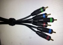
Got several excess RGB cables in the stash that can be sacrificed for the short chassis to PCB and MB to socket links.
I think this would guarantee 75 ohm over the path.
27025 Amphenol RF | Mouser
5-1814823-1 TE Connectivity | Mouser
Don't know if the spdif ground needs to be isolated from the chassis ground? Even if thats the case, isolation washers like those used for chassis mount RCAs could be used. The same piece can be wired to the motherboard spdif out pins via a modified back-plane cover
Got several excess RGB cables in the stash that can be sacrificed for the short chassis to PCB and MB to socket links.
I think this would guarantee 75 ohm over the path.
Attachments
haik, Isn't something like a stock compression (not crimped) end interconnect of the quality the cable companies use acceptable? Those wires hold 75 ohm over long distances and I would think usable in a 1.5 to 3ft (maybe much longer) connection from a PC to a DAC.
I was also looking at RG-179 (Nom. O.D. (in) 0.100) for the short jumpers - if if can be found/purchased in small lengths.
M17/94-RG179 Cable - Buy Coaxial Cable Online from Allied Wire & Cable | Manufacturer of Coaxial Cable
I was also looking at RG-179 (Nom. O.D. (in) 0.100) for the short jumpers - if if can be found/purchased in small lengths.
M17/94-RG179 Cable - Buy Coaxial Cable Online from Allied Wire & Cable | Manufacturer of Coaxial Cable
- Home
- Source & Line
- Digital Line Level
- DAC 2496 (AK4393) DAC KIT With CS8416+AK4393+5532