Imo, Zero, the best way to go is to measure the speakers themselves. It is nice to be precise with component values, but they mean very little compared to the true acoustic response that the xover produces with the drivers...
And, wrt that midrange network, I'd run it in LTSpice to see what the curve really looks like, then measure the "flat" response of the mids and see if the networks are actually doing what you want... of course the actual response with the xovers is the ultimate measurements.
@Kessito - John Dunlavy was the designer/owner, Duntech was his company name, afaik... although there may have been some re-incarnation WRT the company name(s), I do not really recall the history that well.
My point is that there are no "exact values" to be had.
Being too precise may not buy you anything at all except a false sense of security and accomplishment, and a hole in your wallet.
The precison of the values will not effect the operating frequency of the networks enough to worry about - unless you measure it and find a critical window. Then you have to change the values to fit the specific situation. No relationship to the measured or printed value on the parts in terms of sonic results. None at all.
I'm ok with higher quality parts, but look out for DCR on the inductors!! It may or may not play a role in how the network is designed to work.
The Q of the network will change with the DCR. That will in turn alter the freq response. In turn, that may or may not be an improvement in the flatness of response depending on unknowns that can only be measured. Or it may turn out to make a trivial difference when measured, but significant when listened to... impossible to know.
That's why I suggested the simulation and the measurement - with the two interrelating to each other.
My personal opinion is that improved caps and resistors ought to sound different, probably "better". Coils too, but that Q thing might have a big effect.
_-_-bear
Last edited:
Totally agree with bear. No need to break the bank on achieving 100% precision in component values.
Inductor series resistance is one thing you should try to match as it is usually designed for in the crossover.
I've done some tolerance checks on the crossover values in my designs and really +/- 5% is negligible it's effect on the frequency response.
Inductor series resistance is one thing you should try to match as it is usually designed for in the crossover.
I've done some tolerance checks on the crossover values in my designs and really +/- 5% is negligible it's effect on the frequency response.
I better measure the DCR of the inductors before I put them back in. I did mic. the wires to figure out the wire gauge. the big woofer coil is 12ga, all the rest are 16ga except for the big 5.95mH coil which is 20ga.
I plan to replace them with the same gauge coils but I better check the DCR and see if we can match that too!
Thanks
Zc
I plan to replace them with the same gauge coils but I better check the DCR and see if we can match that too!
Thanks
Zc
See, thing is that I would replace them with foil inductors myself... but I'd check the DCR, then plug the whole thing into LTSpice and see what the curves look like. The circuit has resistors whose purpose is to limit the Q in the midrange for certain. So one would want to match the "depth" and width of the dip created by these circuits to the actual response peaks of the drivers.
It's a matter of reverse engineering the xover, and optimizing.
You can just replace, you'll likely get a good result with the better resistors and caps. Beyond that, imo, guessing will not get you that far considering the cost and effort.
If ur not comfortable running it in LTSpice, probably someone reading may volunteer, or you could post for a volunteer too. Someone who runs it all the time can do this pretty darn fast...
_-_-bear
My math indicates that a 3.25 and a 2.8 in series should equal an almost perfect 1.5uf cap. 1.504uf to be exact so I think it was just to come up with a value they didn't have.
But it is very interesting to look at all the places where multiple caps were paralleled to make up a value YET, the 50uF cap in the last midrange tank circuit is one large cap? im not sure the reason for that. why not use 2x 20uf and a 10uf as they have done elsewhere?
But it is very interesting to look at all the places where multiple caps were paralleled to make up a value YET, the 50uF cap in the last midrange tank circuit is one large cap? im not sure the reason for that. why not use 2x 20uf and a 10uf as they have done elsewhere?
See, thing is that I would replace them with foil inductors myself... but I'd check the DCR, then plug the whole thing into LTSpice and see what the curves look like. The circuit has resistors whose purpose is to limit the Q in the midrange for certain. So one would want to match the "depth" and width of the dip created by these circuits to the actual response peaks of the drivers.
If ur not comfortable running it in LTSpice, probably someone reading may volunteer, or you could post for a volunteer too. Someone who runs it all the time can do this pretty darn fast...
_-_-bear
I have no experience with LTspice so if someone wants to volunteer that would be great. I thought of using foil inductors but from everything i have read, and from what i have heard from people here and elsewhere that zero to little benefit is to be had from foil. just a lot of added cost. plus they have lower DCR so i figured that would just mess things up. I might use a foil in the woofer circuit only because finding 12ga air core inductors is hard to do, yet i can find them in foil, and on sale so that location might get a foil.
The inductors are all air core and look to be good enough quality, why not reuse them? I agree with replacing the caps and resistors.
Steve.
I want to keep the stock crossover boards! asis and build all new boards. that way i can always go back or compare the new to the old boards etc. Plus the stock boards aren't laid out very well and they are covered in silicone goop! The inductors are turning out to be the hardest part of all of this!
Zc
I wonder what's the point of the unequal-value capacitors in series, in several locations in this circuit?
Standard practice is to use the parts they already have in their parts bin rather than be specific new parts for every design.
I was curious to know what the crossovers were doing so I set up my SMAART spectrum analyzer system and ran some tests on the crossovers using the transfer function. Here is a composite shot of the response.
This is not 100% accurate as I was using a 4ohm resistive load in place of the actual speaker drivers and I realized after i was done that I also used the 4 ohm load for the tweeter as well when i should have used an 8 ohm load. so that will effect things a bit. BUT this is close enough and repeatable so that after i get the new boards built. I can perform the same test and see if things are the same.
I thought it was interesting none the less!
Attachments
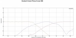
Looking at it for a bit... noticed that the apparent rolloff on the lower side of the mid, and the highs seems to be 3db/oct??!! The woofer seems to be at 6db/oct.
This puts the tweeter down only 12dB @ 250Hz!!
Was this a simulation, or you ran some software with resistors in place of the drivers? If so, then the 4 ohm vs. 8 ohm would put the xover freq of the tweeter even higher (better in terms of IM and power handling) than it really is?
I am not really seeing the effect of what is apparently a notch filter in the mids, maybe it is working to make that 3dB/oct slope. Good trick to do that... unless the scale on the left side of the graph is off?
_-_-bear
I used 4 ohm resistors in place of the drivers. (i should have used 8 ohms for the tweeter). and connected each output to my SMAART spectrum analyzer system.
The woofer is just a 1.5mh inductor in series with the woofer and Dunlavy was famous for using first order networks so the woofer response is exactly what i expected.
the midrange section of the crossover is much more complicated with 2 tuned notch filters that I calculated to be at 3.56khz and 10.6khz which when you look closely at the top side of the midrange section do correspond to the shallow shelf at about 3.5k and the big dip at around 10khz! even the math of the Z of the tuned filters worked out to be .4ohms at 3.5khz and 1.82 ohms at 10khz so figure those in and that should tell us the amount of dip at each section and well...it seems to agree!
The low side of the midrange there are two factors, 1 is the natural acoustic rolloff of the small 4" midrange drivers. I have not investigated to see what they are. the second is the odd RC across the C combo at the front of the midrange schematic. Not sure what that RC does? is that just impedance correction or is that to tailor the slope?
I would imagine that if i had used an 8 ohm resistor on the tweeter section, the response curve would have been moved to the right just slightly and that shallow shelf for the midrange would have lined up a bit better with the tweeters rolloff. But, this was interesting to look at none the less! and it verified my math for the notch filters!
Zc
Right, there is some acoustic roll off somewhere from the drivers themselves - especially the mids and tweeter...
Years back in another place I did give John Dunlavy some flak about the tweeters having to deal with so much energy below their design F3 point. I think it is a real issue as levels go up...
Still, we are seeing ~3dB/oct electrical, yes?
Btw, these curves are almost the classic JAES article from B&O where they showed how their speakers could pass a square wave at 1kHz too... predating Dunlavy's work. Almost, not quite the same. Similar.
_-_-bear
I was curious to know what the crossovers were doing so I set up my SMAART spectrum analyzer system and ran some tests on the crossovers using the transfer function. Here is a composite shot of the response.
The Transfer Function shows the electrical characteristics of the crossover. You may want to do an acoustic sweep instead.

correct that's what I wanted to look at was the electrical characteristics of the crossover. I am building new crossover boards with the same value, just newer better parts and I wanted to be able to compare the new boards and the old boards electrically just to make sure things are the same. I will do a full acoustical test once they are completely finished.
- Status
- This old topic is closed. If you want to reopen this topic, contact a moderator using the "Report Post" button.
- Home
- Loudspeakers
- Multi-Way
- Understanding John Dunlavy's Crossover Designs Crown Prince