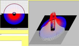
Look at my avatar, it is a field intensity map of a braid conductor inside a braid conductor... note there is no internal field to the inner braid, and there is none outside the outer braid. Energy is confined to between the braids.
j
Now we know where your avatar comes from, it would be nice to see it blown up a bit larger, could you post it?
Use two resistors of value twice that needed. Run them parallel, tied at top and bottom. Run another conductor down in the geometric center of the two. This will be the minimum inductance configuration for two resistors without going to a body braid for the return current.
j
Johny,
Thanks, that is good advice and it makes sense, but there may be a snag. The way I do it, the thermocouples are in two pairs that each balance out and are in close proximity. With the setup you suggest, the top and bottom thermocouple pairs each work into the same direction and are bound to be at different temperatures with different dT/dt's.
As postulated by Johan Cruijff, not just our greatest soccer player, but also a major league philosopher: every advantage has its disadvantage.
vac
Inductively correct, but that energy is stored at a slew rate defined by the circuit resistance, source impedance, stray capacitances, distance to primary source impedance and the physical inductance of the feed wiring. During turn off, the diode will let go based on it's diffusion profile, recombination site density, sweep speed, local parasitic inductances and capacitances. The coupling to external circuits will depend entirely on the current slew rate, while locally it will be the IR drop effect and dI/dL. Turn on will in general, affect anything attached or very close. Turn off can radiate like a B....
j
J
The issue I mentioned was that the energy being turned off is smaller than expected due to the transformer's float or regulation. That doesn't mean don't use soft turn off diodes. All it means is what I thought I said. There is more energy change at turn on than off. Now di/dt or dv/dt is a difficult issue to deal with and has been addressed before. So I can understand that since I used polysyllabic words it might have confused some as to the issues.
Wavey,
A shorted probe still has enough inductance to show the high di/dt turn off spikes as J (N) has brought up. However it does not show the turn on issues as well. Both must be addressed to minimize powers supply noise. But you knew that which is why you raised the issue.
ES
Now we know where your avatar comes from, it would be nice to see it blown up a bit larger, could you post it?
vac
no prob.
It scanned the field, calculating the total magnetic field at every point. The left is the top view, the right is a pseudo 3-d pic, height corresponds with magnitude, scale is black to blue to red. The first pass scan is every 20 pixels for a quick view, then a full pixel to pixel scan to fill in the picture. The full scan took a long time, it was on a Pentium 150.
j
Attachments
Last edited:
However it does not show the turn on issues as well.
ES
Right. Because turn on issue is shunted by opened direct conductivity, while turn off issue is not, so it generates a spike. That calls for proper alignment of wires and components that often costs less during design than replacement of diodes after.
Why I mentioned it, because I suspected that your center tapped picture looks odd to me, as if it was some measurement error similar to what I described. The place in which the center tap connected matters, as well as where to connected the ground crocodile of the probe.
The spikes on the frequency spectrum seem to be around 200 kHz apart. That is I suspect from other measurements the resonant frequency of the transformer!
I am measuring right across the filter capacitor of the demo power supply. There is no chassis. It is just a mass of wires and parts. The ground lead is solder to the junction of the bridges and caps. The input is just at the other end of the cap.
But if there is any particular effect you would like to examine, let me know as there are more tests to be run.
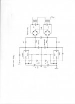
Are the primaries really in series? Anyway, the interesting parts are never shown in most schematics, the exact "how" of the grounds.
As you may see, on John's picture "Ground" signs are misleading. Minus from diode bridges should never ever go to ground. It must go to first filter caps. However, experienced engineers know that intuitively without paying attention, so such "too schematic drawings" are common.
MY power transformers don't NEED shields! ;-)
I see now why you don't believe that power cords don't matter for my amps!

Even sectioned transformers benefit from shields between primaries and secondaries.
Last edited:
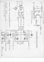
My contribution: I hope that it answers a few questions. It is not the complete CTC Blowtorch power supply, but it is close enough for discussion.
The front end I use for my PS uses much the same lay out. One thing I found really makes a difference is grounding points. One might be tempted to take ground from the diode bridges and then run it straight through to the 317/337 with associated passives. John shows what I measured to really make a difference. Make separate grounding points at the diode bridge and after the 317/337.
vac
- Status
- Not open for further replies.
- Home
- Member Areas
- The Lounge
- John Curl's Blowtorch preamplifier part II