mic input question
I have removed the in / output completely and want to restore the mic input.
I have phantom power sorted out using the +15V lines on the flat-cable. Now I need to build a mic preamp or use a transformer to raise gain. It is unclear to me how much gain is needed (I will use a measuring mic similar to the Behringer)
So I would be much helped by answers to a couple of questions:
1. If using a transformer, what step-up range would work?
2. Suppose phantom power can be connected directly after the transformer without any extra components? Since the transformer isolates the DC from the DCX side.
3. If going with a clone of the original mic pre circuit from the DCX schematics, what opamp would you go for?
Thank you Peter
I have with Pilgham Audio developed exactly that. It's a stand-alone mic preamp on a little PCB and a connector that fits in the digital input hole on the back panel. The connector is a combined XLR (for digital in) with a 6.3mm jack for the mic input.
The board is build, I need to final check it.
Will try to do that next week and report here.
If it works as designed Pilgham will probably offer kits.
I developed this by request from people who build my active DCX mod.
Stay tuned!
jan
Attachments
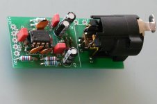
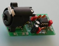
Internals after 1st step
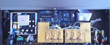
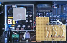
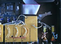
Just for info.
This is how I made space available to play around in the DCX.
Turned the output XLR connector 180º and soldered a prototyping board directly on to them. This gives space to play around with first order filters, buffers, volume control (ldr type?).
Since the proto-board sits quite high I can still put transformers under them if I like.")
Just for info.
This is how I made space available to play around in the DCX.
Turned the output XLR connector 180º and soldered a prototyping board directly on to them. This gives space to play around with first order filters, buffers, volume control (ldr type?).
Since the proto-board sits quite high I can still put transformers under them if I like.
Attachments
Hi Jan,
Glad to offer myself as Guinea pig ;-)
Peter
OK, sounds like a good plan!
I have the unit completed, need to do some basic measurements to make sure that there are no obvious mistake (like swapped supply lines ;-) and then I can send it to you for a user test.
The input is the same as the original DCX complete with 15V phantom power for the Behringer 8000 (?) mic.
jan
Looking forward to the results of this!
I am having issues with my dcx currently - and have given up trying to fix it as the issue illudes me, and have ordered a new one... once I am up and running again and have the active mod installed in the new box, I would be interested in this mod though!)
I am having issues with my dcx currently - and have given up trying to fix it as the issue illudes me, and have ordered a new one... once I am up and running again and have the active mod installed in the new box, I would be interested in this mod though!
)Didden i/o Mod, Burson Discrete OPAs
Hello,
i Thought to post my "tweek" of the Didden active i/o..
Installtion of Burson Discrete OPA's!!
Firstly, +/-9v avaliable from the i/o board is too low for these power hungry modules,, the THD+N is too high (thanks to a thread on here).. Much better at +/-18v.
So I built an external power supply to power these modules, and modified the Burson IC socket adapter so not to get power from the existing i/o board.. Of course, the GND of this new power supply would need to be connected to the GND of the DCX power supply.. Which I did with a fly-lead coming from pin 4 of the power supply connector on the DSP board..
(my aplogies for such poor photos)


However,, I am getting very loud humming!! I measured this hum with TrueRTA and the analyser shows 2 big spikes at 50Hz and 100Hz.. (mains hum??)
When I use a non-modified discrete module and rely on i/o power, no humming..
Obviously to do with using 2 separate power supplies??
Any ideas??
Ta
CM
Hello,
i Thought to post my "tweek" of the Didden active i/o..
Installtion of Burson Discrete OPA's!!
Firstly, +/-9v avaliable from the i/o board is too low for these power hungry modules,, the THD+N is too high (thanks to a thread on here).. Much better at +/-18v.
So I built an external power supply to power these modules, and modified the Burson IC socket adapter so not to get power from the existing i/o board.. Of course, the GND of this new power supply would need to be connected to the GND of the DCX power supply.. Which I did with a fly-lead coming from pin 4 of the power supply connector on the DSP board..
(my aplogies for such poor photos)
However,, I am getting very loud humming!! I measured this hum with TrueRTA and the analyser shows 2 big spikes at 50Hz and 100Hz.. (mains hum??)
When I use a non-modified discrete module and rely on i/o power, no humming..
Obviously to do with using 2 separate power supplies??
Any ideas??
Ta
CM
Last edited:
Looks nice!
The hum may have to do with the connection of the external power ground to the internal DCX ground. If it's only 50/100Hz it is probably not rectifier ground loops; in that case you'd have more harmonics.
Did you put in a direct connection between the external supply ground to the DCX?
jan
The hum may have to do with the connection of the external power ground to the internal DCX ground. If it's only 50/100Hz it is probably not rectifier ground loops; in that case you'd have more harmonics.
Did you put in a direct connection between the external supply ground to the DCX?
jan
Back in Business!
Power supply repaired and main board swapped out on my DCX - Now all working again! I did not realise just how lost I would be without Jan's output board! Not just the volume control, but having lived with it for years, having to take the output from the DEQ instead really showed up the shortcomings of the original Behringher units! No clear smooth sweet 3D audio! I just wanted to turn it down all the time, whereas now it is back working I just want to turn it up! - Many thanks for the aid, Jan and co!
Power supply repaired and main board swapped out on my DCX - Now all working again! I did not realise just how lost I would be without Jan's output board! Not just the volume control, but having lived with it for years, having to take the output from the DEQ instead really showed up the shortcomings of the original Behringher units! No clear smooth sweet 3D audio! I just wanted to turn it down all the time, whereas now it is back working I just want to turn it up!
- Many thanks for the aid, Jan and co!Did you put in a direct connection between the external supply ground to the DCX?
jan
Hi Jan,
Yes, a direct connection from the center tap (GND) of the external supply, to pin 4 of the seven pin power connector on the DSP board.
(maybe photo dont show too good, but i have terminated a binding post at each end, for easy connecting of the 2 GND's..
@fredsonqc: Yes perhaps, but this is the fun of DIY
Anyhow, Burson products are not so expensive here in Aus..Even with loud hum, (and music turned up loud) I notice improved channel separation which has improved soundstage and 'space'.. So maybe not so bad ;-)
Ta
CM
Last edited:
Assuming there's also a ground connection between the two units via de XLRs, there *could* be a ground loop.
Difficult to say what to do, but try to limit ground to a single connection.
What you could try is to tie the two chassis together only through the pin 1 of the XLRs - that's what they are meant for.
But grounding is always a bit messy...
jan
Difficult to say what to do, but try to limit ground to a single connection.
What you could try is to tie the two chassis together only through the pin 1 of the XLRs - that's what they are meant for.
But grounding is always a bit messy...
jan
Hmm.. Not quite sure what you mean here..
Ground the 2 chasis together thru pin 1?? Which two chassis you mean?? The external supply has plastic case,, only the shield around the transformer is Earthed (you can see in photo).. GND is not Earthed in either device. I may be confused here but,, the (power) GND of both DCX and external supply have been connected together, at pin4 of X3 (DSP power connector)..
How does pin 1 of XLR fit into this?? Perhaps the interconnects to my amps?? I use 2 core shielded (balanced cable at DCX) and connect pin 1 & 3 at the RCA end (amp) keeping the cables "balanced as long as possible"..
Without the external power supply in use, Eg, using power from i/o board for the discrete modules, I get no hum.. Interesting??
Ta
CM

Maybe this gives clues to where problem may exist..??
This is directly across speaker terminal with no music playing,
volume at -10dB (on the remote screen)
View attachment 282060
Thanks..
CM
If you have followed the standard way then the grounds/earth of the two units are connected through pin1 of the XLRs.
Then there's the direct connection from the aux supply to the DCX supply pin 4.
This can form a ground loop which might cause hum.
However, looking at your spectrum I see a lot of higher line harmonics which are typical of not just hum but a 'chainsaw' buzz. This indicates that there's a common ground path of the rectifier/reservoir cap which causes that ground return current to cause a voltage across for instance a small impedance in that ground path.
The voltage resulting is added to the input voltage because the ground ref of that input voltage is elsewhere. It's probably easier to draw then to explain.
Bottom line: look for ground wires or traces that carry return currents from the rectifier/reservoir cap, probably in the aux supply. Try to ground the two grounds of the pos and neg cap close to each other and close to the xformer ground tap. That localises the currents with the buzz. Then from that common point run a wire to the DCX ground, OR connect the common point to the XLRs pin 1. Or both (but sets up another ground loop...).
Difficult to exactly say what to do in detail with out having the unit in front of me.
jan
Thanks Jan!
You were correct.. After reading your post, and then studying the article on here about "grounding", it occurred to me that I had incorrectly wired my external PSU's ground connection
I had taken GND (external psu) directly from Center Tap, and not "further down" the circuit board where the +/-18v output is.. So I re-wired the ground connection to where the actual GND output was, at the other end near the voltage output.. Instantly, the bad hum/buzz went away..
However!! Further reading this great article, I realised that connecting this GND's at X3 'pin 4' was also incorrect, and needed to be at the chasis star GND connection.. Once I did this, hum/buzz vanishes almost completely..
However, when I mute/unmute on the remote, or change volumes etc,, I get loud "pop" with every button press on the remote..??
I think it might be better if I just power these modules with the +/-15v available from the Didden Linear PSU instead of trying to combine 2 power supplies..
Can the Didden Linear PSU handle an extra 300mA..?? Do you see any issues here with taking power from X3 pin 1 & 2.. At least I wouldn't need to worry about grounding
Cheers..
CM
You were correct.. After reading your post, and then studying the article on here about "grounding", it occurred to me that I had incorrectly wired my external PSU's ground connection
The voltage resulting is added to the input voltage because the ground ref of that input voltage is elsewhere...
Bottom line: look for ground wires or traces that carry return currents from the rectifier/reservoir cap, probably in the aux supply.
jan
I had taken GND (external psu) directly from Center Tap, and not "further down" the circuit board where the +/-18v output is.. So I re-wired the ground connection to where the actual GND output was, at the other end near the voltage output.. Instantly, the bad hum/buzz went away..
However!! Further reading this great article, I realised that connecting this GND's at X3 'pin 4' was also incorrect, and needed to be at the chasis star GND connection.. Once I did this, hum/buzz vanishes almost completely..
However, when I mute/unmute on the remote, or change volumes etc,, I get loud "pop" with every button press on the remote..??
I think it might be better if I just power these modules with the +/-15v available from the Didden Linear PSU instead of trying to combine 2 power supplies..
Can the Didden Linear PSU handle an extra 300mA..?? Do you see any issues here with taking power from X3 pin 1 & 2.. At least I wouldn't need to worry about grounding
Cheers..
CM
Last edited:
- Home
- Source & Line
- Digital Line Level
- Behringer DCX2496 digital X-over