In another thread I was asking what is the recommended way to look at and measure a floating voltage using the oscilloscope. The problem is that the oscilloscope probe is earthed and effectively you will earth the component under test, usually with very undesirable results (like meltdown).
There is some good information here:
http://www.newark.com/pdfs/techarticles/tektronix/FFM.pdf
Solutions that were mentioned in the other thread were:
a) use an isolation transformer on the oscilloscope to "float" its own earth.
This solution means messing with the power side of the scope, not sure how you'd go about earthing it (it has a huge metal chassis) and it still leaves both its probes connected to the same "virtual earth". In any case I do not have a mains isolation transformer and it sounds dangerous.
b) use the two probes together (only the tips) and then "invert" one channel and "add" function on the scope in order to see the curve. This is the "A minus B" technique.
This technique works, sometimes, but it ties down both channels on the scope, and it also requires a reference ground, so cannot be used in a lot of cases where you want to measure a true floating voltage without any references to the ground.
I have therefore decided to experiment with an isolation device that I can put between the component under test and the probe.
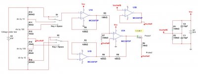
I have come up with the simple circuit below, a textbook differential amplifier. I have tested it and it works OK, but more tests to come. If successful I was thinking of building it in the tiniest package possible, so itself looks like a probe, or a probe extension and can be used easily.
Please let me know what you think.
There is some good information here:
http://www.newark.com/pdfs/techarticles/tektronix/FFM.pdf
Solutions that were mentioned in the other thread were:
a) use an isolation transformer on the oscilloscope to "float" its own earth.
This solution means messing with the power side of the scope, not sure how you'd go about earthing it (it has a huge metal chassis) and it still leaves both its probes connected to the same "virtual earth". In any case I do not have a mains isolation transformer and it sounds dangerous.
b) use the two probes together (only the tips) and then "invert" one channel and "add" function on the scope in order to see the curve. This is the "A minus B" technique.
This technique works, sometimes, but it ties down both channels on the scope, and it also requires a reference ground, so cannot be used in a lot of cases where you want to measure a true floating voltage without any references to the ground.
I have therefore decided to experiment with an isolation device that I can put between the component under test and the probe.
I have come up with the simple circuit below, a textbook differential amplifier. I have tested it and it works OK, but more tests to come. If successful I was thinking of building it in the tiniest package possible, so itself looks like a probe, or a probe extension and can be used easily.
Please let me know what you think.
Attachments
All you have to do is disconnect the 3rd wire (earth)
on the (scope) mains plug and make sure no other
equipment is attached. This puts the ground of the
scope @ the potential of the second output, but it works.
Agreed! This is what I do, but, WARNING! This is potentially dangerous and cannot be recommended here.
Those experimenters confident enough to do such things do not need advice such as this.
AKIS, why don't you give real examples of what you are trying to measure?
Your circuit is effectively what a 'scope differential plug-in does.
You will have significant errors in CMRR, bandwidth and DC accuracy unless you spend the equivalent of a decent TEK diff plug-in will cost you!
Your circuit is effectively what a 'scope differential plug-in does.
You will have significant errors in CMRR, bandwidth and DC accuracy unless you spend the equivalent of a decent TEK diff plug-in will cost you!
I am not It trying to measure tube-like voltages, but simply to be able to measure anything on any circuit, without shorting it to the ground.
My first experiment was OK, except the frequency response is weird. It is correct until about 80KHz and then it starts to rise with a peak at about 500KHz and then falls rapidly.
I am not sure if this is an artifact of the way I have mounted the bits on the breadboard, or the breadboard itself (parasitic capacitances).

I will try to fix it. Seeing as differential probes cost thousands of dollars.
Not necessarily. Check this one out.
Your diy creation might work fine, but basically it's unproven and untested safety-wise. I'd strongly suggest you limit its usage to separated extra low voltages only!
According to IEC, separated extra low voltages (SELV) are < 50 Vrms and < 120 VDC. These are high enough to give you a shock, though...
Disconnecting a scope's safety earth or protective earth (PE) is potentially dangerous. Those that know the dangers may do so at their own risk, but they must never recommend such procedure. When measuring high floating voltages, the only thing that can be recommended is a certified differential probe and that rules out diy. This may sound exaggerated, but when it comes to safety, it's "safety first".
Last edited:
I have tried 4 different op-amps with the exact same results: LM833, LM4562, TL082 and MC33072.
The problem seems to be around U3A - it is very sensitive to any parts "moving" around it, and placing a small cap across the 100K feedback resistor has dramatic, but uncontrollable effect.
The problems seem to start at about 50KHz and peak at 500KHz. Anything below 50KHz measures very correctly. I will see if this is "simulate-able" , else I am giving up")
The problem seems to be around U3A - it is very sensitive to any parts "moving" around it, and placing a small cap across the 100K feedback resistor has dramatic, but uncontrollable effect.
The problems seem to start at about 50KHz and peak at 500KHz. Anything below 50KHz measures very correctly. I will see if this is "simulate-able" , else I am giving up
Not necessarily. Check this one out.
Your diy creation might work fine, but basically it's unproven and untested safety-wise. I'd strongly suggest you limit its usage to separated extra low voltages only!
According to IEC, separated extra low voltages (SELV) are < 50 Vrms and < 120 VDC. These are high enough to give you a shock, though...
Disconnecting a scope's safety earth or protective earth (PE) is potentially dangerous. Those that know the dangers may do so at their own risk, but they must never recommend such procedure. When measuring high floating voltages, the only thing that can be recommended is a certified differential probe and that rules out diy. This may sound exaggerated, but when it comes to safety, it's "safety first".
OK, but still hundreds of pounds
It is fascinating that what I am trying to do has already been "built" commercially since I had no idea that active, differential probes even existed.There are a few reasons to try and build this circuit at home :
1) saves one hundreds of pounds (or thousands of dollars)
2) much preferable to removing the earth lead from your scope
3) I do not really care for 100MHz - just 500KHz will do nicely - of course if the circuit is good for higher frequencies then so much the better.
4) I do not care to measure thousands of volts - just 100 Volts AC peak is also fine. Anyway, my scope has a limit at 400V - same precautions as to when using the passive leads apply.
5) I do not care about super fine accuracy down to a few mV at GHz - I do not need to make a "certified" laboratory instrument.
So I think that when I meantioned "floating voltages" some people instantly thought "many hundreds or thousands of volts in high tension photovoltaic circuits, or tube amplifiers" but I say again this is not the reason to try and do this.
"So I think that when I meantioned "floating voltages" some people instantly thought "many hundreds or thousands of volts in high tension photovoltaic circuits, or tube amplifiers" but I say again this is not the reason to try and do this."
Then why didn't you say so? Accuracy in asking will get you much more appropriate advice!
Then why didn't you say so? Accuracy in asking will get you much more appropriate advice!
"So I think that when I meantioned "floating voltages" some people instantly thought "many hundreds or thousands of volts in high tension photovoltaic circuits, or tube amplifiers" but I say again this is not the reason to try and do this."
Then why didn't you say so? Accuracy in asking will get you much more appropriate advice!
I am trying, I am trying
If interested, here's one more good reference:
A Primer on Differential Measurements, Types of Amplifiers, Applications, and Avoiding Common Errors
A Primer on Differential Measurements, Types of Amplifiers, Applications, and Avoiding Common Errors
In my limited experience the differential probes where the amplifier is close to the tip have good common mode rejection and have been useful for looking at noise. Though very expensive for what they are. The types which have a seperate box with BNC connectors for conventional probes haven't worked much better than setting the Oscilloscope to add Channel 1 and Channel 2 and invert Channel 2.
You have used rather high value resistors. Your frequency response irregularities may be due to stray capacitance and the input capacitance of the amplifiers. A few pF across R3, R9 R7 and R8 might help.
You have used rather high value resistors. Your frequency response irregularities may be due to stray capacitance and the input capacitance of the amplifiers. A few pF across R3, R9 R7 and R8 might help.
Akis
You may have a look on this one.
http://www.diyaudio.com/forums/equipment-tools/189545-implementing-y-out-oscilloscope-8.html#post2622342
It works for me.
Check out the IC datasheet to see if it is OK for your requirements
George
You may have a look on this one.
http://www.diyaudio.com/forums/equipment-tools/189545-implementing-y-out-oscilloscope-8.html#post2622342
It works for me.
Check out the IC datasheet to see if it is OK for your requirements
George
- Status
- This old topic is closed. If you want to reopen this topic, contact a moderator using the "Report Post" button.
- Home
- Design & Build
- Equipment & Tools
- Measuring floating voltages with oscilloscope