
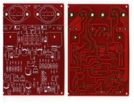
The outputs are marked EXPP 8733 and EXPN 8733 I think they are Mosfets (from what I've heard) The driver stage is SM2178A and SM2177A . Interesingly enough the capacitors have stickers with hand writen 12.15 , code (two of them are 12.16) not sure what it means , date or the result of matching. They will be due to change soon. Power rail is +- 40V. I think I'm shooting myself on the foot here since I'm looking for matching Exposure preamp , a model VII
Hi, I have seen Avondale website and ncc200 board really there is no thermal coupling of vbe multiplier with output stage.Hi VibroKing$
If you go to the Avondale site, you'ii see the NCC 200 differences are more. For instance, a coil is used in the output for stability. When you change an amplifier and its compensation in particular, stability is affected. That version does need it.
If you understand audio design and how to stabilise a power amplifier both electrically and thermally, fine but very few people do and many just simulate until it works acceptably with generic models. In real life, the audio may not be so good or thermal runaway destroys it at some time in the future.
The design you posted is a generalised original Naim drawing covering all models at the time and includes the VI limiters TR7 & 8 which clones do not. I understand that no amplifiers were never exactly to this published design.
There are many choices for substitute parts and I have changed quite a few types for people who wanted to try something else. BC549B,C or 550B,C are generally used at the input and best matched for beta and Vbe as well as possible. This is easy with a suitable DMM. In most cases of substitution, remember that increased beta, Hfe or gain leads to instability. Sometimes it is critical. Check for overheating of parts and the output stage when playing roullette with parts.
The other semis can be BC546, 2N5401 etc. for MPSA06 and TR5, the Vbe multiplier. The drivers need something - anything better than the clone's TIP41/42! There are several good drivers but I found no improvements over originals MJE243/53.(some high-gain types caused oscillation) The problems are VAS and output types and whatever the rationale, slugs like MJ15003 power transistors just don't work properly in the clones. IMO, if you listen with genuine Sanken or Toshiba high Ft types, the difference to the sound in an otherwise capable clone will be obvious and more exciting, if I can put it that way.
If you read back to Ruwe's posts, you'll find a lot of experience and good advice there.
also I am forced to use 2n5550/2n5400 instead mpsa06/56.
mpsa06(vceo=80v Icm=.5A Pd=.625W hFE=100 fT=100MHz)
2n5550(vceo=140v Icm=.6A Pd=.625W hFE=60 fT=100MHz) "higher voltage hardest transistor" (hFE)
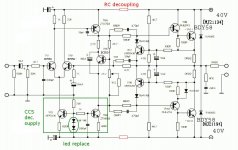
I think the basic schematics is enough old and quality of capacitor (tantalium) and selected transistors make the difference.
Also in basic schematics the only decoupling is CCS after in revised sch. they have added RC filter supply.
Simulatiom with spice does not consider parasitical effects that often generate oscillations
The Exposure amp. details are interesting. With those drivers, I'd say it was BJT, not Mosfet. Perhaps it has just been described as having a mosfet sound but you could check this from the much higher bias current. That also means better heatsink connection than what we see. I think we can assume from "P" and "N" suffix it will be complementary rather than Quasi design.
VibroKing$, it's unfortunate that you can't get proper VAS transistors. To be clear, the total power dissipation of 95% of small, TO92s will give you trouble at medium power every time. Those that do have the minimum 1W dissipation required are usually too slow and have higher Cob than required. The VAS is probably the beginning of great sound in most BJT amps - don't compromise here.
Also consider that the Miller compensation capacitance is the sum of the cap. fitted, the transistor Cob and strays. Wrong parts= wrong compensation. The Ebay cloners have tried a few parts and now they supply 2SB647/2SD667. These are repackaged TO126 types 2SB649/D669 which are good drivers but too slow here. A similar scaled-down pair are BC639/40 for BD139/40 and Philips types might even work - lasting longer than 600 mW types anyway.
You are right about no thermal coupling, as in Naims too. Scary, isn't it but at low levels of bias, with a suitable circuit and mounting position (top of the case), they remain in control. Many audio reviews said at the time, that the amplifiers need about 30 min. warm-up to sound good. Now you can see why.
Does anyone have a high resolution copy of this schematic? The transistor types are not labeled on the board and I didnt get a schematic with my kit. I have tried to contact the seller many time to no avail....here if the kit i am referencing
NAP-140 Classic NAIM CLONE Mono Audio Power Amplifier KIT with Sanken Transistor | eBay
If you have one and could email it to me that would be great...
I need to be able to cross reference the Q1,2,3....etc with the transistors given in the kit...even a list of which transistor types corresponded to the labeling on the board (Q1,2,3...) would be fine too...
Thanks!
Jeff
This is LJM's board as advised earlier. It is sold by many Ebay traders. If youi visit Tubeshunter, Along1986090 shops for instance you should find a schematic posted there. Beware the original schematic which may confuse because parts are all original types.
If you read this thread, you'll see several schematics posted by people with the same question. I once found my schematic as an email attachment with dispatch confirmation - didn't see it for weeks! Since then, it's been on the sellers item description page. Look around.
If you read this thread, you'll see several schematics posted by people with the same question. I once found my schematic as an email attachment with dispatch confirmation - didn't see it for weeks! Since then, it's been on the sellers item description page. Look around.
Hi everyone . I haven't read all of the thread so forgive any unwanted intrusion . I had a number of discussions with the late Julian Vereker boss of Naim Audio . He was always very frank and willing to share how the amplifier worked . I have a feeling I did kick the first CD player into life with something I said to him . It was along the lines of regardless of how good he thought 16 bit linear quantization was he could build the best CD player in the world . To which he said perhaps as he had not considered FM radio very good before building a tuner . The CD player was seen about 18 months after that . There is much more to that story and it would need a few pages and I am sure not that interesting ? I had the feeling that Julian did not think that the design of the amplifier circuit the key element of a Naim design . It is only a power op amp . I think it is a world betting power op amp and very advanced compared with typical designs of 1971 . I also feel it is an original concept regardless of the fact that it is said to be modified H C Lin ( not Linn ) and looks like RCA designs . I think I met it's originator Alan Mornington West , however never spoke to him mores the pity . The all NPN output stage was a passion of J V and was very rightly defended as the NPN devices of 1971 were far faster than the PNP's . The small diode in the bottom half of the complimentary feedback output pair ( other side a Darlington ) does a very good job of mimicking the symmetry of a fully complimentary output stage . JV is quoted as saying ( approximately ) NPN and PNP transistor pairs are as similar as men and women of the same height and weight .
I know many similar amplifiers , all of them made after Naim started . I feel the key element to all is the correct use of the VAS transistor and it's associated capacitor . I would even say the inclusion of a 16 R emitter resistor worth trying ( less loop gain , however helps the previous stage , it will do a few other things, sonically softer ) . Everything else is covered by Douglas Self in his books although not specifically Naim . Mr Self and I do not agree about that resistor and have told each other so . It is not about negative feedback or local feedback . If choosing to stick with the Naim design I would select a transistor of the highest possible gain ( 400 + like genuine 2SD756 and 2SB716 high gain group [ general advice for all amps , NPN or PNP as required , pin out different ] ,some I bought recently were 150 , perhaps fakes , 2n5551 repackaged ? ) . If so myself and Mr Self have no argument . Be careful when looking at that . Start with 100 pF VAS cap and work down ( scope required ) . Use COG/MPO ceramic or silver mica ( all sound good although other ceramics usually not ) .Never use polystyrene although sonically excellent .It will let go eventually and take your speakers out . Surface mount 1205 types can be excellent .
I am fairly certain at sometime I had a discussion about most of the important points . However Tantalum capacitors I never dared discuss as I had been warned not to .
Hi Nigel
Being clone kits and ultre cheap (within the reach of newbs and dabblers), there is not a lot of choice for parts selection and only a few suppliers of bare PCBs. This virtually stops people from DIY building and sourcing better parts. The design might otherwise be ignored though, given that all NAIMs since the late 70s remain faithful to the topolgy and there is little to gain choosing between models.
The larger problem is parts availability and limited choice. You mention transistor speed and the availabilty of necessarily fast VAS transistors is shrinking because the need for them in the market has shrunk drastically since the demise of CRT displays and "through-hole" discrete devices generally. The old parts are nowhere to be reliably found now and these current 2SB647/D667types are drivers actually, which happen to have a high Ft. Cob however, is sub-optimal IMHO. The original are ZTX653/753 1W TO92 which are are still available but at $1 ea, the cloners have looked elsewhere.
Hi Ian . I love what you are doing and will give it any support I can . I even mount , surface mount transistors on wires to get what I need these days . Check out BCV61 anyone who wants a state of the art current mirror . The low voltage is usually not a problem as the VAS transistor protects them . You often need my 16 R to allow the current mirror to balance properly . I had even thought of having them encapsulated and putting wires on them . If anyone does it you own me a pint .
On that point my introduction to current mirrors was via Kendle Perry who worked for Burr Brown last I heard ( write me anyone who knows him ) . He loved Crimson Amplifiers . When we get to the pub tonight my Pro Audio chums and me I promise Crimson will be discussed . They were geniuses . The only amp universally thought of to be good by the Pro Audio bunch and us lot . C Audio is I guess the Naim of the Pro Audio world .
Any questions anyone wants to ask please do . I know quite a lot about all Brit amps . The very interesting one is the Sinclair Z30 . It is not like the Naim exactly , however it is very special . What was so bad about it was also so good . All it needed was modern parts ( and a bias system , clever how they did it ) . I am told that when certain gurus of the 1970's were asked how should they learn about Hi Fi they were told to buy a Sinclair and make it work . Then add the largest power supply they could . If you look at the spec of a Sinclair it is outstanding . My friends and I are thinking to make Sinclair Clones just for the hell of it .
Buy BC550 and 560 I think they are coming to the end . Transistors are not like tubes . Generally speaking if it has the spec it will work . Interesting what you say about TV parts . It applies to tubes also .
Cheap transistors of note are D44/45 H . BD139/140 MJE340/350 . BC550/560 2N4401/4403 . 2SA1085 . 2SA970 . 2N5551 . BC337 .
Bipolar | CPC
Ian . Don't know if anything useful here . CPC is the retail division of Farnell . Sometimes cheaper then Farnell ( Newark ) trade . I didn't look for specifics so good luck with it .
Ian . Don't know if anything useful here . CPC is the retail division of Farnell . Sometimes cheaper then Farnell ( Newark ) trade . I didn't look for specifics so good luck with it .
Hi,
I was able to figureit out using some schematics I goggled....mine has the B647/D667 types you mentioned but in place of the TIP mine has a A1930 and its complement type (dont remember offhand).
So would it be of benefit to find the ZTX type and replace the B647/D667? can I just drop them in without changing anything else?
I did do some upgrades to the original kit...all resistors are 50ppm PRP 1/2w except for the output resistors (used original until I can souce better ones like Caddock). Also, I used a Wima 10uf/63v on the input cap and another Wima for the Zoble....the electrolytics were replaced with Nichicon kZ for the larger ones (kit came with 100uf so I used 100uf) and for the remaining 10uf caps I subbed some Muse bipolar type i had...mine came with Sanken output transistors...I happen to have some MJL21194 (i think thats what they are), would those work better or at all?
What is the minimum and max rail voltage I can use on this amp? Calls for 40v but I have a few toroids that will get me either slightly under (35v) or over (50v).....was thinking of using the 50v and building a regulated supply with some LM317HV (max of around 57v i think) which i have on hand...or just using a resistor before the power supply to bring the voltage down some....and there is Antek which I could just buy exactly what I need....
Thanks,
Jeff
Couldn't resist to join in . I think you should build the 40 V regulator . LM317 is about 1MHz . You need 50 MHz ( TID if not ) . Take a good transistor ( D44/ 45 would do if the 80 V version still available , use a few ) . Run them on a simple zener diode with filtering capacitor ( 1 uF , called an amplified zener as a design ) . Beats a LM317 any day . You will be on the way to a NAP 250 . There are better ways and the transistors can be re used . You will be very surprised how it changes the sound .
I will have a look tomorrow to see if anything else comes up . Hope everyone will be building 250's by then .
I will have a look tomorrow to see if anything else comes up . Hope everyone will be building 250's by then .
Last edited:
Hi Tekko . I have seen the designs for class A amps using LM317 and it makes quick and easy CCS . 1MHz is actually a very wide bandwidth for a class A amp . The John Lindsly Hood is such a design . 350 kHz can be made to be OK . If you switch off the bias to a class B amp you will see how it works with crossover distortion . Loosely speaking the amplifier will fight hard to correct the error . If used as a sub woofer amp it is even possible to use an amp like this . Some class B FET amps can be set to zero bias with almost acceptable results . By about 5 kHz the bias is badly needed . The fast Ft fights hard up to a higher frequency . If a slow PSU is used it is felt by some designers that the problems return that we were trying to escape . Effectively the LM317 is swinging with the outputs and switching off with them . This is the dreaded TID . Transient Inter-modulation Distortion . Said by many not to exist and not by this route . I beg to differ and JV more so . The fastest transistors went into NAP 250 and the fastest of those into the power regulator . There are shunt regulators which can be slower . I think they are harder to design .
I found a little design using a Darlington pair . The first transistor can be ultra fast . A small cap across the zener to reduce noise ( 100 uF + 1 Uf ) . A heat sink will be required as with the 317 . If 57 V that's up to 100 watts for a party giver ( +/- 17 V at 3 amps ) . Realistically music is 1/6 full power . If we said 15 watts per side we would be about right . 1 degree per watt per channel per voltage rail or 0.25 degrees per watt for all devices . I reckon going to about half that 0.5 per watt and fitting a thermal cut out as Naim did would work ( about 65 Cecilius) . It is a bit daunting when the voltage to be reduced is so high . The transformer needs to be about 300 VA or larger . For the 317 the current limit is 1.5 A , I should say it's not enough , however it would be OK'ish . The voltage is too high , LM317 can be adapted for that ( in design notes on the net ) . I've seen 317's used at 400 V ( Marantz Model 8 and 9 ) . 10 Amps peak is not out of the question as a transient .
Power Supply Regulation
Last edited:
Hi,
in place of the TIP mine has a A1930 and its complement.......
......So would it be of benefit to find the ZTX type and replace the B647/D667? can I just drop them in without changing anything else?.....
....I happen to have some MJL21194 (i think thats what they are), would those work better or at all?......
If you go back a few pages you'll find the same 317 regulator idea considered and a fancy schematic even. The maximum voltage is 40V, set by the input stage transistors,VAS transistor Vceo, drivers etc. If you blast anything with high supply voltage you increase dissipation so you need to amend the design and often components to cope. For DIY newbs, I suggest not. If your rails are 35V, you won't hear any difference, If they are 43, you may pop the VAS and input stage. You can readjust bias currents if you are experienced but the cost if you are not is $$ and grief. The original VAS parts were already on the edge.
Reverting to original parts is not simple, US pattern for small parts is EBC and Japanese BCE. Just check data sheets by Googling the part number and selecting your favourite free archive site. Try Datasheetarchive and pick a reference with enough detail to give diagrams. Single page lists only compare specs.
MJL 21194 are great TO3s but only 10% of Toshiba 2SC5200 or genuine Sanken 2SC3858 speed. This will kill it in the water for having a Naim sound which relies on having maximum speed trannies throughout (you have fake 3858s) This has all been discussed in recent pages. Please read.
IMO any transistor will improve on TIP41/42 as drivers. They work and reduce concerns of excessive gain and oscillation that could occur using modern drivers, but really don't allow the speed required. The original MJE243/53 are a minimum, I would think. Compare Ft of transistors, this is the transition frequency by which gain has dropped to zilch.
The emitter and output resistors are MO types, I think and you should stick with lowest inductance available. Brands can add nothing to SQ but the most suitable types probably will.
Last edited:
I see it's 50 V which is better . I still would like to think 1 degree per watt .LM 317 is 37 V from memory . I suspect a Naim will work down to +/- 25 if bias is adjusted to suit ( same standing current ) . What do you guys use as standing current (bias ) . For a Rotel it was 43 mV through 0.22 R emitter resistors or 20 mA . Rotel RA 820 is in some ways how the ideas drifted down to mass production . I always said if I can't have a Naim give me a RA 820 . It might interest people to know that the transistors ZTX etc were Ferranti , they changed name for whatever reason ( it was a big deal I seem to remember ) , Naim were petrified as they depended on them . Now we have more choice even allowing for diminishing stocks . The transformers also were a problem , Holden and Fisher who stopped producing ( would you believe I took about 10 to the dump the other day , I beg someone spotted them , big PA amp stuff ) . That was a calamity as Naim were very precious about them . Naims often blow our mains fuses we have in our plugs , they have unusual inductance ( that's good ) . Will look in tomorrow if this old age pensioner is allowed ?
Just a last word . 40 V regulated is worth about 50 V unregulated in power terms if talking typical commersial designs ( ironically the voltage to be considered for regulation is 50 V ) . Thus an NAP 250 would give 70 W RMS and would have a go at 280 watts transient into 2 ohms . The NAP 160 was a lower power although idling at nearly the same voltage . It is terribly ambitious to do a regulated design due to the amount of metal needed to dissipate the heat . Heaven forbid I said it what come next . Has anyone tried switch mode PSU's with a clone ? It could work !
BDY58
On many clone schematics the BDY58 is mentioned as output transistor. Was it really used in the original design?
Has anyone tried switching-mode transistors like the 2N5038? Some clone kits come with BUV20 or BUV21. I used BUV52 to replace some fried 2N3055 in a quasicomplementary amplifier and they sounded much better than the original.
- Home
- Amplifiers
- Solid State
- NAP-140 Clone Amp Kit on eBay