After many years of exclusively using solid state gear, I decided to try modern tube amp. I had no intention to spend several thousand dollars on that new toy, so my only real choice was one of Chinese amplifiers, as many of them are available for under $1000. Speakers in my main system are 90dB efficient, so even though room is not that big, I thought that I need a sufficient power. This requirement excluded almost all SET amplifiers (yes, I know there are some 30-40W amps with 845 or similar tube, but they were out of my defined price range). I did some search and decided to get one of Yaqin amplifiers. My final choice was MC-100B. I already have an almost perfect preamp (old Yamaha CX-1000), so my target was a power amplifier. Yaqin actually does not make any dedicated power amplifiers, but many of their so-called "integrated" are no more than power amplifier with volume control pot at the input. I decided to get the most powerful one - MC-100B. It is advertised as reaching 60W per channel, built as dual mono on a single chassis and does not have anything I DO NOT need like remote.
Yaqin does not have any official distributor in the US, so I ordered this amplifier from one of eBay sellers (tabnaac) in Canada. He is dedicated to Yaqin brand and has almost perfect feedback history. There were zero problems with order, and in about a week
I got a very heavy box with Canadian shipping label. Again there were no problems with packaging, and soon shiny chromium plated amplifier was sitting on a stand which I bought for it. It is very heavy and produces large amount of heat, so I couldn't put it into my equipment rack. I new this in advance, and made arrangement to get a dedicated stand (VTI AGR404-01S), which arrived even before Yaqin was deliver to me.
I have only one set of speakers in my music room, and since I already have solid state amp powering them, I needed a speaker switch. I spent a lot of time searching Internet for a something that can be used to connect one pair of speakers to two amplifiers, and didn't find that many options. Most speaker switches designed to connect several pairs of speakers to a single amplifier. Many of advanced ones have a volume control etc. But this is not what I needed. My goal was to have a switch as transparent as possible and do not do anything I didn't need. I also found that many switches are designed to work with relatively low power amplifiers (under 100W), but my solid state rig delivers over 500W to 4 Ohm load. Finally I found a device that was almost perfect - OSD ATM-7. This is remotely controlled (it actually comes with IR remote) switch that can connect seven pairs of speakers to two amplifiers (or seven amplifiers to two pairs of speakers). It prevents connecting the same speakers to two amplifiers at the same time
(which will likely result in amplifier failure). I jumped on opportunity to get one on sale, and got this switch. It is weird, but it is only available from a single on-line store, however it was not branded specifically for that store. It actually didn't have any label on it, which could attribute it to the manufacturer. So it is indeed "no-name" unit. But nevertheless, it works perfectly, exactly as advertised.
So after I connected everything together, I turned on Yaqin and let it run for an hour. After 30 minutes or so I checked bias of tubes (MC-100B has fixed bias, which needs to be adjusted once in a while). It was spot on at 52mA for each tube (recommended setting is between 50 and 60mA). To easily compare my SS amplifier with new Yaqin, I adjusted volume in both of them using pink noise source and sound level meter. Yaqin does not have balance control, so I adjusted volume in each channel of my solid state power amp (it has the separate volume pots for each channel) to match new tube amp, one channel at a time. I made both channels matching within 0.2 dB.
Now it was time to listen. I prepared several CDs, which I know very well, with different kind of music. From large classical orchestra, to chamber orchestra, to jazz, to classic rock. I went through all these disks (about 10 of them) in several days. I found that at moderate volume levels (when I only get under 20 Watts from amplifier) it was very hard to hear the difference between SS and tube amp. I also asked my wife’s (she is a trained musician) opinion and she couldn't hear it too. But after some time and good concentration I was able to reliably identify Yaqin sound.
First was bass. In by SS amp the bass is very tight, and it is perfectly aligned with the rest of the sound. With Yaqin bass was a bit fatter. It seems that tube amp is not able to fully control speakers in the lower octave. On some type of music it is not pronounced at all. But where you have large drums recorded with low compression, and thus keep all dynamic and punch, here you go - tube amp simply couldn't match precision of SS amplifier.
Midrange was exactly the same with either SS amplifier or Yaqin. I tried hard, but never was able to identify any tube signature in it.
Now treble. What I found was that Yaqin had it a little muted. It was like light veil over tweeter. You can't hear it in any electronic sound, but on good acoustical recording it didn't produced the level of transparency, and sense of space around percussion instruments like bells and cymbals, which I used to. This again was only heard on records with only little compression applied to them.
As a result of listening sessions, I can say that there is nothing mystical about tube amps. They (at least when we consider moderately priced gear) sound close to good SS amplifiers. They do have some deficiencies, but they are not very pronounced, and might not be recognized when record quality is not exceptional, or speakers and room do not permit to resolve very fine details of the sound.
So after two weeks of listening it was time for a test bench. I searched hard trying to find any published measurements of Yaqin amplifiers, but got empty handed. Since there are no official distributors of Yaqin in any country I know of, there is no one to deliver a sample unit to any of usual testers (both for on-line publications and printed magazines). Thus I decided to run few tests with the goal to make them available to anyone, who consider Yaqin brand. And also as a starting point for tweaking this amplifier (which was the original goal behind purchasing it). In my next post I will provide details, results of measurements and description of my initial attempt to improve the sound of Yaqin MC-100B.
Yaqin MC-100B - not as powerful as advertised, but still a good value. Part 2.
This is a second installment of my experience with Yaqin MC-100B amplifier, which includes measurements and notes on my attempt to tweak it in a search of better sound.
After a week of listening sessions I took Yaqin to my lab for testing and possible tweaking. First I decided to measure basic parameters like output power, THD, noise level to get sense of what you can get out of the box and set the baseline for modifications. In my measurements I used the BK Precision function generator, Rigol digital oscilloscope, EMU 0404USB audio interface with TruRTA and RMAA software packages for precise measurements. In all tests I used 8 Ohm dummy loads connected to both channels. I did all tests in Yaqin in “power amplifier” mode, using front inputs. MC-100B can be used in “integrated” amplifier mode, when it activates source switch and also increases sensitivity by reducing overall negative feedback, but I never had intention to use it that way, so I didn’t bother to try.
Initial measurement results were quite positive. Noise level was below generally below 90 dB, with slight 60 Hz hum and its harmonics visible on FFT results. But they all were below 75 dB. That corresponded well with my listening experience, where I only heard slight hum when my ears were within an inch from speaker. Yaqin does not use choke in the filter, but two 470uF capacitors in each channel (MC-100B is indeed almost completely dual mono design, with only last stage bias supply shared) do a very good job to eliminate any power supply related noise.
Next I measured bandwidth. Again there were no surprises here, and it was completely flat within audio spectrum, slow declining from 30 kHz upwards. But I found a resonant peak at around 270 kHz. This is probably due to resonance in output transformer (which is common in tube amplifiers). This shouldn’t usually be a problem unless you listen to SACD or other content with excessive ultrasound noise. Looking forward, I tried to reduce this problem with some success, I will provide details later.
Now comes most important part. When I tried to measure THD and IMD at rated power (60W), it was clear that there is something wrong. I saw all FFT screen filled with distortion products. When I connected oscilloscope to the amplifier’s output is was clear why – I saw almost square signal instead of expected 1 kHz sine wave. Yes it reached required 21 Volts RMS on 8 Ohm load, but this is not was you expect from audio amplifier. So first point taken – rated power has nothing common with reality in this amplifier. I then tried to reduce volume to the point when I didn’t see obvious distortion on the oscilloscope (which usually means THD below 1%). And I found that only if output signal is below 15 Volts RMS (which corresponds to 28 Watts), I do not see much of distortion. I ran tests at that power level and got reasonable results with THD + noise at 0.7%, and IMD (using 60 + 6000 Hz, 4/1 amplitude tones) at 1.5%. But that only was at base frequency of 1 kHz. When I tried to measure THD at 8 kHz, results were rather poor. Oscilloscope again showed me why – at 8 kHz, I had to reduce output signal to 12 Volts (18 Watts) to get visually correct sine wave. It all means that full range power limit of MC-100B is only around 18 Watts. I repeated measurements at 1 Watt of output power, and THD was at much better 0.07% level, which was expected.
Recalling 270 kHz peak, which I found in my bandwidth test, I decided to see if there is any possible instability. I used 1 kHz square signal from functional generator. It has rise and fall time of 20 nS. And I found what I expected – there was significant ringing with close to 300 kHz frequency, which continues for 4 – 5 cycles before settling down. There was definitely stability problem with MC-100B, which needed to be addressed. Since Yaqin uses higher feedback when in “power amplifier” mode, I repeated just this test using “integrated” mode. Ringing was still there, but reduces to 2 – 3 cycles. This test run confirmed that problem was with instability caused by global feedback, and when it was reduced, ringing was reduced too (which is textbook behavior).
Overall results from initial tests were in line with expectations from Chinese design and relatively cheap implementation. In out-of-the-box form MC-100B provides adequate performance for someone who decided to get into tubes. But there was really no reason to prefer it to any competent solid state amplifier, other than for aesthetic reason – it really looks nice with its black and chrome color palette and glass tubes glowing with orange lights. One distraction was a bright blue LED on the front panel. It would be more appropriate to use orange LED there, and I will likely do that this swap one day.
So now it was clear that my Yaqin needs some work to be done on it to make it sound better.
First I found schematic diagram. I could do reverse engineering on PCB myself, but someone already did it, so I used his work (I do not know what is the origin of it, so I do not know who I need to thank for it). One copy of schematic is available at http://www.ict-net.net/100B2.jpg Of cause, I made sure that it matches to what I found when I opened bottom panel of Yaqin. One error just popped up – R5 resistor is indeed 510 K, not 39 K as you can see there. Another was that volume control pot is 20 KOhm, not 50 KOhm as shown on drawing. These both are minor differences, which practically do not change the sound.
When I verified that diagram is correct, I entered it into circuit simulation program (I use Spectrum Software’s Microcap 9). It has models for 12AX7 and 6SL7 tubes, but not KT88. I did extensive Internet search again and found two different SPICE models for KT88, as well as alternative models of other tubes. Microcap permits switching models quickly, so I used them alternatively trying to match results I found in real thing. Another problem was that I didn’t have parameters of output transformer. There was no any labels on transformer (yes, I did remove black cover can), so it seems to be a custom design for this amplifier. But I found detail specification on several output transformers for KT88 tubes available from different vendors and tried to use closest in term of winding resistance (I do not have LCR meter on hand to measure inductance, maybe someone will do it and publish results, which will be helpful for other tweakers).
Now having the results from initial simulation run, I started with measuring actual amplifier. First thing I noticed is unexpectedly low B+ level. From diagram you can see that secondary winding of power transformer should deliver 360V, which corresponds to 509 Volts expected on B+ bus. But I saw only 410 Volts. I checked my line power and it was at 117 Volts, which is close to nominal 120. Moreover, filament heater supply was close to 6.3Volts. Which means that power transformer works as specified (I actually calculated that it was likely designed with 115 Volts source in mind). I recall reading messages on some forums about Yaqin amplifiers supplying 6.9 Volts to filaments, but this is not my case. So it is likely that Yaqin redesigned their power transformers by increasing primary windings. Actually if I potentially increase source voltage to get 6.9 Volts at filament, it will have specified 360 Volts on main secondary.
I did find several application notes for KT88 tube, and they always specified more than 500 Volts of the plate to get 60 – 80 Watts of power. In my case I only had 400, which explained power limit at half of what KT88 is able to deliver. There is no real workaround for Yaqin design, other than replacing power transformers. But this is expensive proposition, as they are sold for $120-160 each (and you need two for dual mono design like MC-100B). So the only thing I could do with tweaking was to make sure that I squeezed last drop of power from Yaqin and make sure that all other stages are as linear as possible.
After I adjusted power supply parameters in Microcap model equal to what I measured, I got a reasonable match between DC simulation results and actual measurements. Difference was less than 10%, which I consider accurate enough.
Now it was time to do some optimization. Yaqin uses SRPP circuit as first stage. Usually SRPP topology is used for a relatively low impedance load, but here it was 1 MOhm load from Schottky phase splitter. There are two variables you can play with here: R3 and R4 resistors. From commonly known SRPP stage calculations for 1M load, you would expect R3 and R4 to be 2.4 KOhm. But simulation with goal to get highest output with lowest THD resulted in different values: R4 at 1K and R3 at 3K. This change will significantly reduce bias at grid of Q2 (MC-100B uses direct connections though first three stages, probably trying to avoid using capacitors in the signal path), so to keep idle current of Schottky stage, it was reasonable to reduce R8 to 43K. Another possible improvement lies in phase splitter plate load resistors. Yaqin decided to use the same 47 KOhm resistors in both sections of it. But it is recommended to have R7 higher (or R6 lower) to balance the circuit. Simulation results recommended either 43K/47K or 47K/51K pair. It was hard to simulate final stage without exact specification of output transformer, but using reasonable guess, I got results close to expected for maximum output power in 30 – 40 Watts range.
Now it was time to implement changes in real amplifier and see what I can get. This will be a topic of my third article.
Yaqin MC-100B - not as powerful as advertised, but still a good value. Part 3, final.
This is a third and final part of my analysis of Yaqin MC-100B, where I describe my attempt to improve its sound.
To make sure that amplifier works best in all power range from zero to clipping, I measured it at three points of output power – 1Watt, 8 Watts and at clipping point (whatever this limit was for every modification). I also disconnected global feedback circuit, assuming that if I will be able to make amplifier most linear without it, I will always improve results by adding it back. So all tweaking was done without global feedback and measured numbers reflect that.
At first I measured Yaqin distortion values in stock form. Here is what I got (all numbers are in dB relative to main signal):
At 1 kHz 2nd harmonic 3rd harmonic
1 W -54 -60
8 W -43 -43
32W -24 -34
At 8 kHz
1W -43
8W -28
32W -19
I didn’t measure second harmonic for 8 kHz signal, as it is outside of measurement range for 48 kHz sampled EMU interface.
Now after I modified circuit based on best simulation results I got:
At 1 kHz 2nd harmonic 3rd harmonic
1W -51 -59
8W -35 -41
32W -32 -34
At 8 kHz
1W -41
8W -24
32W -24
Here goes simulation… As you can see, we have some improvement at maximum power, but poor results anywhere else. I repeated simulation with different tube models, but still didn’t get anything better than stock, when I measured it. I do not know if it is a deficiency of simulator, or tubes parameters are too far from ones used in models. But it looks like simulation is not very helpful for tube based designs (I never had so much of discrepancies in transistor circuits).
Now it was time to decide what to do without relying on simulation. First thing I decided to try was based on lower than expected B+ level. I decided to increase plate voltage at least in first three stages. This is easy to do in Yaqin, since it has two RC filters to clean power for input tubes. I decided to start with R14 and R15. I shorted R14. This resulted in increase of plate voltage from 338 to 365 Volts in Q3. All other plate voltage increased too. From oscilloscope picture it was clear that I could get higher peak-to-peak signal at the grid of KT88 before onset of distortion. Increase was about 20%, which I would consider significant. Another thing to consider was final stage bias. 50 to 60 mA range specified by Yaqin is reasonable when you have plate voltage at 500 Volts. KT88 is specified to have 35-40 Watts (depends on version) of maximum plate dissipation. For 500 Volts on the plate it means 70 mA. It is recommended to use 70-80% of it at idle for AB class amplifier, which translates into 50–55 mA of recommended idle current. This is in line with what Yaqin recommends. But if we have only 400-410 Volts at plate, we can increase idle current if there is a need for it. I tried all range between 55 and 85 mA, measuring THD at 1 kHz, and found that the best result I can get was at 85mA. This is a little high (34 Watts), but considering that KT88-98 tubes used in Yaqin are relatively cheap, I can live with lower tubes’ life expectancy.
Another change I tested was to make Schottky circuit plate load different as usually recommended. When I reduced R6 to 43 KOhm I noticed improvement in second harmonic level of about 5 dB. I tried to get it even lower, but result was worse. So I decided to stay with 43/47 KOhm pair.
Now I did a final round of measurements with all changes implemented. Now I had:
At 1 kHz 2nd harmonic 3rd harmonic
8W -49 -51
16W -44 -43
I also noticed that I can get better output level at 8 kHz before onset of clipping from 18 to 21 Watts.
Now it was time to restore global feedback and test amplifier as a whole. I did full test and found that I can get at least 35W before obvious signs of clipping at 1 kHz. At 15 Watts I got THD level at 0.03% and IMD at 0.17 for 60+6000 Hz signal. At higher power levels THD slowly increased to 1% and IMD to 5 %. But overall useful power (under 1% IMD) was below 35 Watts at 1 kHz and about 25 Watts for 8 kHz. These are respectable numbers and should provide good listening experience for almost all types of music and relatively sensitive (over 90 dB) speakers.
Now it was time to address ringing in amplifier after applying global feedback. From simulation I noticed that there is not enough of phase reserve at high frequencies. This is a common problem with tube amplifiers when they use output transformers. I verified that there is no phase problem in the first three stages. Thus all my attention was concentrated on the final stage with a pair of KT88. I did some research and found one possible solution – shunt primary winding of the output transformer with capacitor and resistor. One practical example from 1950th for KT88 based amplifiers included 1000 pF capacitor in series with 1 KOhm resistor between plate and screen grid connections of the output transformer (it has to be applied to both tubes in push-pull circuit). I decided to follow this example. The result was positive. It reduced ringing from 4-5 to 2 cycles. It also visibly reduced overshoot at fronts for at least 50%. I decided that it is enough of improvement, and didn’t try to get it any better.
Now it was time for listening tests again. I used the same disks as before, but added some old vinyl records from 60th and early 70th. What should I say – now there was no difference between my solid state amplifier and Yaqin at all. I tried all records on which I used to hear artifacts before, but there was nothing now. Until I got to power level over 35W (my main power amplifier has peak meters), there was no way I could distinguish Yaqin from my solid state rig.
As a result I can say that tube amplifier, when it operates within power limits and loaded with moderately easy to drive speakers, has no difference in sound from competent solid state amplifier. Again there could be many different reasons why someone chooses tube rig today, but sound shouldn’t be one of them.
Comments are welcome.
Interesting work, but you seem to base your conclusions about tube amplifiers on one sample. It is always dangerous to extrapolate from a single example.
The basic topology of the amp is fairly standard, although there is no need for an SRPP at the input. The Chinese seem to like SRPP, though. The 6SN7 phase splitter is probably a fashion statement, as it has too low mu to operate well without a CCS tail. KT88 output should be fine, if it had sufficient supply voltage and a good transformer. So my conclusion is that this amp is intended to push the fashion buttons for a certain type of audiophile rather than actually perform well. It has the usual Chinese problem of not meeting the claimed specs.
Don't regard a cheap Chinese amp as typical of tube amps. They are designed to sell, not to sound.
Yes, just like transistor amps, topology, component selection and component quality make huge differences!
The chinese make very boring amps TBH, some mediocre circuit design with odd tube choices and a dull GNFB loop draped over the top.
It's a testament to the tube that they sound as good as they do - can you imagine what their transistor ones sound like? This best thing about the chinese amps is that they are a cheap way in to learn about tubes and some can be modded to sound pretty good.
I would have recommended the Yaqin MC-10L over the 100B, but there is scope for making it into a project amp.
Yaqin are not too bad but certainly for Music Angel you need to ground the chassis to mains earth and check for capacitors that are over-voltage.
hi, did you check the output traffo turns ratio and find out loading?
if i were to redo this amp, i would have dc coupled the output grid to the cathode of the emitter follower and controlled output bias from the 6SN7 grids instead....
i would choose a Mullard 5-20 or HK citation5 type input front-end....
i am not a big fan of the 12ax7 in a hifi amp, i like them best in a guitar amp....
Hi,
did you manage to try EL-34 is MC-100B?
Can it just replace the KT-88 or does it need some tweaking?
I currently have an MC-10L and I would like to upgrade to MC-100B. But the question is: is it really an upgrade?
What I hate most about the MC-10L is the RCA plug at the back. They are low quality, and if you have tight cables, some might come off.
Serge
No, I didn't yet. I still run original KT88. I plan a next round of tweaking later in the summer though.
I think the main difference from MC-10 is "dual mono" design. It helps with tweaking too - you can instantly compare parameters before and after while amp is on the bench.
I think the main difference from MC-10 is "dual mono" design. It helps with tweaking too - you can instantly compare parameters before and after while amp is on the bench.
I do not think MC-10 is very different. They used EL-34 tubes there, and skipped cathode follower. I actually want to try EL-34 in MC-100B. Considering low B+, it could be an option. The question is if it is more linear than KT-88.
First of all, I would like to thank you for your work and your diligent way of testing this amplifier, the most important point you make is that when a lot of global feedback is applied, tube amps sound like any solid state amp.
I would recommend KT77, which is like the little brother to KT88, and roughly equivalent to EL34. But the point really is not whether KT88, EL34 or KT77 is linear enough. If you move to this direction, you could up the values of R20 and R22, as per the EL34 or KT77 datasheet. I also strongly suspect that the output transformer impedance ratio would be spot on for the "smaller" tube types, because this amp was originally designed to work with EL34's it seems. Pretty easy to check impedance ratio with a tone generator and a scope.
The point is that this circuit is operating KT88's in a voltage too low . Tubes like to be pushed and are more linear when operated in higher voltages, in general.
Another bonus to switching to an appropriate tube type, is that they need lower power to be heated up, i.e. your power transformers will run cooler.
BTW 160$ for one power transformer?????
Last edited:
I'd like to bring my view on the Yaqin MC100-B. I have this amplifier for over 4years now and I have had the opportunity to compare it with many solid states and tube amps from different price range.
I can now say that IMO, once properly customised this amplifier gives a very good sound and at least as good as famous market amps up to 6x or 7x its original price.
The mods that I've made on mine:
- Mundorf silver oil 1uf caps
- Shuguang GEKT88 (bias at 45ma max)
- 2x 6SN7 Sylvania NOS
- 2 x 6SN7 Russian NOW
- 2 x 12AX7 Psvane treasure
- HV delay (1min20)
- Amp mounted on spikes
Hi Everyone, thought i would share my experience with this amplifier. I got it off Ebay delivered including taxes for £500. Ordered it thursday midnight and it was at my front door midday the following monday. Wow was quick.
Anyway i connected it up and had a listen. It sounded terrible to be honest. I reached for my soldering iron and got a circuit diagram. I removed the feedback loop completely. Got rid of the volume control and selector switch from the circuit. I then wired the front set of phono sockets to the grids and added a 47k grid stopper in series. I then noticed that the grid leak resistor was actually 510k and not 39k as per the drawing. I fitted 47k instead. I then removed the capacitor across the input stage cathode and made the two cathode resistors one value.
I threw away the ecc83s and 6sn7s that came with the amplifier and fitted mullard and sylvania respectively. I switched on and biased the output stage to 65ma having measured an anode voltage of approx 420Vdc.
Time to listen. I was gobsmacked by the sound I heard coming from my B&W683s. Sublime is the word. Amazing imaging and depth, with massive space around all the vocals and instruments. I played disc after disc and the hours flew by. I didn't want to switch it off. The sound continued to improve as the amplifier burnt in. Sounding good on CD and Vinyl.
6 months on and i'm still grinning. I have since replaced the ECC83s with Russian 6n2ps and modifed the PCB to take into account the different heater arrangement. I split the track between pins 4 and 5 with a junior hacksaw blade and moved the heater supply wire from pin 9 to the now spare pin 5. I've also replaced the 6 0.22uf caps with wima MKP 10s. This has added another dimension again. The amplifier sounds so fluid and natural and makes listening a real pleasure.
I use it with a Conrad Johnson PV10a and a heavily modded Mission PCM4000 and Technics 1210 with SME V.
My only wish is that the amplifier had more power, but for the money I can't complain. I punches well above it's weight.
I will post any further mods I make. Next mod is to use a bunch of Elna Cerafines leftover from another project in the power supply. Should spice things up a bit more.
Bye for now")
Anyway i connected it up and had a listen. It sounded terrible to be honest. I reached for my soldering iron and got a circuit diagram. I removed the feedback loop completely. Got rid of the volume control and selector switch from the circuit. I then wired the front set of phono sockets to the grids and added a 47k grid stopper in series. I then noticed that the grid leak resistor was actually 510k and not 39k as per the drawing. I fitted 47k instead. I then removed the capacitor across the input stage cathode and made the two cathode resistors one value.
I threw away the ecc83s and 6sn7s that came with the amplifier and fitted mullard and sylvania respectively. I switched on and biased the output stage to 65ma having measured an anode voltage of approx 420Vdc.
Time to listen. I was gobsmacked by the sound I heard coming from my B&W683s. Sublime is the word. Amazing imaging and depth, with massive space around all the vocals and instruments. I played disc after disc and the hours flew by. I didn't want to switch it off. The sound continued to improve as the amplifier burnt in. Sounding good on CD and Vinyl.
6 months on and i'm still grinning. I have since replaced the ECC83s with Russian 6n2ps and modifed the PCB to take into account the different heater arrangement. I split the track between pins 4 and 5 with a junior hacksaw blade and moved the heater supply wire from pin 9 to the now spare pin 5. I've also replaced the 6 0.22uf caps with wima MKP 10s. This has added another dimension again. The amplifier sounds so fluid and natural and makes listening a real pleasure.
I use it with a Conrad Johnson PV10a and a heavily modded Mission PCM4000 and Technics 1210 with SME V.
My only wish is that the amplifier had more power, but for the money I can't complain. I punches well above it's weight.
I will post any further mods I make. Next mod is to use a bunch of Elna Cerafines leftover from another project in the power supply. Should spice things up a bit more.
Bye for now
It's great to read about such mods. Would you have a schematic showing your mods?
I'm using this amp as integrated amp so can't get rid of the volume pot.
My mods: caps replaced by 1uf silver oil mundorf, high voltage 1min20 delay, amp on spikes, tubes: GEKT88, 6SN7GT Raydon and CV181Z, 12AX7 Shuguang Treasure.
What other mods would recommend?
Cheers
Sent from my GT-N7100 using Tapatalk 2
I have an MC-100B, and haven't done any modifications to it (I know little about electronics and circuits, I'm a software guy).
I'm wondering if I can just drop some KT77s in and have it work without circuit modifications. The KT77 is a beam tetrode just like the KT88, and they're less than half the price of KT88s, which is low enough to be worth experimenting with. The EL34 is a pentode, not a beam tetrode, so I'm curious that you think it might be compatible. (Again, I know little about audio circuits and the differences between tubes)
If either of these are swappable, what would I run the bias adjustment at after installing them?
Thanks!
Charles.
I do plan some minor mods to this thing. For starters, I intend to remove the volume pot from the signal path of the front input. For the integrated part, it makes sense. But for the front input, I would rather have a clean input from my phono stage (which has its own volume control)
Also, after 5 years of ownership the super bright blue LED burned out, so I'll probably replace that with a nice (dim) orange one. But that's really the extent of my ability.
Charles.
Also, after 5 years of ownership the super bright blue LED burned out, so I'll probably replace that with a nice (dim) orange one. But that's really the extent of my ability.
Charles.
Help asked upgrading yaqin MC-100b caps and resistors
Greetings from Spain and happy new year¡¡¡
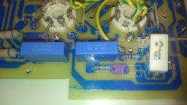
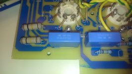
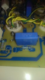
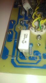
I am the proud owner of a Yaqin MC-100b. So far I am fully satisfied with the amp, it sounds incredible good to me, much better than expected. Let me start by saying that I am not a technician at all. I just have very elementary electricity concepts, some soldering skills and of course lots of care. When adjusting bias for the first time I realized one of the pots was broken. Therefore, with some Christmas holidays ahead I decided to take the PCB to replace it and, once being there, I thought it would be worth upgrading the amp caps (I’ve read very good reviews about the Murdoff/Solen oil films and the Wima caps) and ceramic resistors as suggested by many of you in this forum. Which brand and specs should I use to get more bass and if possible greater definition?. The amp does currently have 6 PILKOR X2 0.22uF(220nK) 275v OFC caps and four 5 watts 10 ohms ceramic resistors (regardless of the PCB legend saying that they should be 3 watts 10 ohms¡¡¡). Should I change all the 6 caps to get the best possible results? What about the resistors, any suggestions? Should I go for 3 watts? I am very sorry to post such an elementary question to you guys, but as said before I am a newbie in this world.
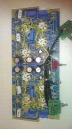
I will try to post some pics for further clarification,
Kindest regards, Marianom
Greetings from Spain and happy new year¡¡¡
I am the proud owner of a Yaqin MC-100b. So far I am fully satisfied with the amp, it sounds incredible good to me, much better than expected. Let me start by saying that I am not a technician at all. I just have very elementary electricity concepts, some soldering skills and of course lots of care. When adjusting bias for the first time I realized one of the pots was broken. Therefore, with some Christmas holidays ahead I decided to take the PCB to replace it and, once being there, I thought it would be worth upgrading the amp caps (I’ve read very good reviews about the Murdoff/Solen oil films and the Wima caps) and ceramic resistors as suggested by many of you in this forum. Which brand and specs should I use to get more bass and if possible greater definition?. The amp does currently have 6 PILKOR X2 0.22uF(220nK) 275v OFC caps and four 5 watts 10 ohms ceramic resistors (regardless of the PCB legend saying that they should be 3 watts 10 ohms¡¡¡). Should I change all the 6 caps to get the best possible results? What about the resistors, any suggestions? Should I go for 3 watts? I am very sorry to post such an elementary question to you guys, but as said before I am a newbie in this world.
I will try to post some pics for further clarification,
Kindest regards, Marianom
Attachments
Couples/Pairs 6SN7 are specular: V1-V4 and V2-V3 ??
Hi The couples of 6SN7 are specular: V1-V4 and V2-V3 ???
or the pairs are V1-V3 and V2-V4
That's in order to use 2 different couples of 6SN7
And someone knows the plate voltage of KT88 in the MC100-B (for 230VAC) ??
That's to calculate the bias adjustment;
the 0.55 V suggested by manufacter at what % of plate dissipation put the point of work for the tube??
Thanks
Last edited:
Greetings from Spain and happy new year¡¡¡
I am the proud owner of a Yaqin MC-100b. So far I am fully satisfied with the amp, it sounds incredible good to me, much better than expected. Let me start by saying that I am not a technician at all. I just have very elementary electricity concepts, some soldering skills and of course lots of care. When adjusting bias for the first time I realized one of the pots was broken. Therefore, with some Christmas holidays ahead I decided to take the PCB to replace it and, once being there, I thought it would be worth upgrading the amp caps (Ive read very good reviews about the Murdoff/Solen oil films and the Wima caps) and ceramic resistors as suggested by many of you in this forum. Which brand and specs should I use to get more bass and if possible greater definition?. The amp does currently have 6 PILKOR X2 0.22uF(220nK) 275v OFC caps and four 5 watts 10 ohms ceramic resistors (regardless of the PCB legend saying that they should be 3 watts 10 ohms¡¡¡). Should I change all the 6 caps to get the best possible results? What about the resistors, any suggestions? Should I go for 3 watts? I am very sorry to post such an elementary question to you guys, but as said before I am a newbie in this world.
I will try to post some pics for further clarification,
Kindest regards, Marianom
Do not chanve capacitors and high power resistors. There is very little value in it. Try mods I described in my three posts here. You will be much better satisfied with results than simpy swapping components to a different type.
I have an MC-100B, and haven't done any modifications to it (I know little about electronics and circuits, I'm a software guy).
I'm wondering if I can just drop some KT77s in and have it work without circuit modifications. The KT77 is a beam tetrode just like the KT88, and they're less than half the price of KT88s, which is low enough to be worth experimenting with. The EL34 is a pentode, not a beam tetrode, so I'm curious that you think it might be compatible. (Again, I know little about audio circuits and the differences between tubes)
If either of these are swappable, what would I run the bias adjustment at after installing them?
Thanks!
Charles.
You will better use KT90 and set idle current to 100mA. It will indeed improve sound.
Couples of 6SN7 in yaqin mc100b - plate voltage
Hi
The couples of 6SN7 are specular: V1-V4 and V2-V3 ???
or the pairs are V1-V3 and V2-V4
That's in order to use 2 different couples of 6SN7
And someone knows the plate voltage of KT88 in the MC100-B (for 230VAC) ??
That's to calculate the bias adjustment;
the 0.55 V suggested by manufacter at what % of plate dissipation put the point of work for the tube??
Thanks
- Status
- This old topic is closed. If you want to reopen this topic, contact a moderator using the "Report Post" button.
- Home
- Amplifiers
- Tubes / Valves
- Yaqin MC-100B - not as powerful as advertised, but still a good value.