I was looking for a well designed compact DAC and surprisingly, I just couldn't find anything decently priced. It must have USB and hi-rez capability.
Ebay - Junk designs with TE or AK chips, no ASRC.
HRT Music Streamer - Good USB, basic DAC, hamstrung by power and layout.
MF M1DACA - Exactly what I wanted, poor design especially power delivery, basic parts quality.
Diyaudio - Nothing close to what I was looking for.
Aussie SmartDAC - Close but USB audio support dubious.
So I went and build my own. My main inspiration came from the Benchmark DAC1. It's based on TAS1020B for USB with a AD1896 96kHz ASRC. Next is the Bel Canto DAC3.5VB. Stereophile rated that as a class above the Benchmark DAC1. The DAC3.5VB has a SRC4392 ASRC running at 192kHz feeding PCM1792 DAC with OPA1632 diff opamps for the output. Alas, it has no USB. Both products are also a bit pricey while just falling short of my requirements.
My goals are:
1) Compact (for possible inclusion in a future DIY integrated amp - that seems to be a trend with many amps featuring crappy PCM27XX 16-bit/48KHz DAC).
2) High rez USB, at least 24-bit/96kHz but with no proprietary drivers for Windows.
3) ASRC (AD1896 was initial choice but SRC4392 seemed easy enough to use plus it allowed for more features).
4) PCM1794A DAC. I didn't like the Wolfson stuff. ESS is not diy-friendly.
5) Well designed power delivery with individual high performance regulators for each supply, no shared supplies, latest TPS7A4901/3001 15uV regulators for the analog section. Ample and properly laid-out decoupling.
6) No signal coupling caps.
7) No exotic but good quality parts throughout. 10ppm crystal oscillator for digital. Metal MELF resistors for the analog section with film PPS caps. LME49720 for I/V and OPA627 for line driver.
8) Hand solderable, so nothing smaller than 0603 and no BGA's.
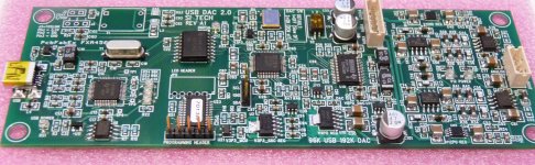
The first prototype has been completed and initial tests complete. It is working and I'm most pleased with the results.
Features:
1) 24-bit/96kHz USB Class 1 audio with asynchronous interface using TAS1020B.
2) 24-bit/192kHz digital coax input via transformer isolation.
3) USB is fully isolated via ISO7240C.
4) All inputs upsampled to 192kHz via SRC4392 ASRC.
5) PCM1794A DAC with LME49270 I/V and OPA627 for single-ended outputs.
6) Ten (yes 10) low noise LDO regulators.
7) PSOC for auto-input selection, LED sample rate display and ASRC configuration. PSOC idles in sleep state with internal clock and CPU core shutdown.
8) PCB layout that meets my own rules and goals, which are inline with industry high-speed digital and analog expectations.
Some pictures below. I guess it shows that I'm not so good with a camera.
Please note that this is a completed design. So you can make your own if you're looking for stuff like Crystek clocks, Burson opamps, Bybee filters, 22000uF filtering, FET I/V, etc. I have realistic goals to meet (and a family to feed).
")
PS: PCB size is 142mm X 50mm
Ebay - Junk designs with TE or AK chips, no ASRC.
HRT Music Streamer - Good USB, basic DAC, hamstrung by power and layout.
MF M1DACA - Exactly what I wanted, poor design especially power delivery, basic parts quality.
Diyaudio - Nothing close to what I was looking for.
Aussie SmartDAC - Close but USB audio support dubious.
So I went and build my own. My main inspiration came from the Benchmark DAC1. It's based on TAS1020B for USB with a AD1896 96kHz ASRC. Next is the Bel Canto DAC3.5VB. Stereophile rated that as a class above the Benchmark DAC1. The DAC3.5VB has a SRC4392 ASRC running at 192kHz feeding PCM1792 DAC with OPA1632 diff opamps for the output. Alas, it has no USB. Both products are also a bit pricey while just falling short of my requirements.
My goals are:
1) Compact (for possible inclusion in a future DIY integrated amp - that seems to be a trend with many amps featuring crappy PCM27XX 16-bit/48KHz DAC).
2) High rez USB, at least 24-bit/96kHz but with no proprietary drivers for Windows.
3) ASRC (AD1896 was initial choice but SRC4392 seemed easy enough to use plus it allowed for more features).
4) PCM1794A DAC. I didn't like the Wolfson stuff. ESS is not diy-friendly.
5) Well designed power delivery with individual high performance regulators for each supply, no shared supplies, latest TPS7A4901/3001 15uV regulators for the analog section. Ample and properly laid-out decoupling.
6) No signal coupling caps.
7) No exotic but good quality parts throughout. 10ppm crystal oscillator for digital. Metal MELF resistors for the analog section with film PPS caps. LME49720 for I/V and OPA627 for line driver.
8) Hand solderable, so nothing smaller than 0603 and no BGA's.
The first prototype has been completed and initial tests complete. It is working and I'm most pleased with the results.
Features:
1) 24-bit/96kHz USB Class 1 audio with asynchronous interface using TAS1020B.
2) 24-bit/192kHz digital coax input via transformer isolation.
3) USB is fully isolated via ISO7240C.
4) All inputs upsampled to 192kHz via SRC4392 ASRC.
5) PCM1794A DAC with LME49270 I/V and OPA627 for single-ended outputs.
6) Ten (yes 10) low noise LDO regulators.
7) PSOC for auto-input selection, LED sample rate display and ASRC configuration. PSOC idles in sleep state with internal clock and CPU core shutdown.
8) PCB layout that meets my own rules and goals, which are inline with industry high-speed digital and analog expectations.
Some pictures below. I guess it shows that I'm not so good with a camera.
Please note that this is a completed design. So you can make your own if you're looking for stuff like Crystek clocks, Burson opamps, Bybee filters, 22000uF filtering, FET I/V, etc. I have realistic goals to meet (and a family to feed).
PS: PCB size is 142mm X 50mm
Attachments
Last edited:
Thank you for your feedback.
Hi Sonic,
I am aware of the better jitter filtering spec of the AD1896 ASRC compared with the SRC4192 which is pin compatible. However, the part I used is the SRC4392 which has better specs and is NOT pin compatible. My initial design actually used the AD1896 (easy to solder SSOP28 package and no firmware required). I settled on the SRC4392 because it offers more features (namely the 4-port input digital receiver) and it can do 192kHz. I know Benchmark amongst others say 192K upsampling is no good but hey, Stereophile rated the Bel Canto DAC3.5VB which uses the SRC4392 running at 192kHz as a class above the DAC1. Can't really call that a bad choice now, eh? Even the best-of-the-best M1 Bricasti uses AD1955 with opamps for I/V.
If you run the calcs, you'll find the LME49720 to have more than sufficient specs for I/V duty here (192kHz X4 for margin, so calc for 1MHz). Now I know this is subjective, some will say you shouldn't even run opamps at all. You'll find the LME49720 in the DAC1 PRE. So that's pretty good enough for me. Besides the Musical Fidelity uses el-cheapo JRC5532 and Stereophile both raved about it and it measured well. In my case, I am limited solely by the need for a dual op-amp for I/V. I just couldn't find anything better than runs off +/-12V supplies. I stuck the OPA627 as the final diff-SE driver because I wanted very low output offset. Here, I can take any opamp and I have the OPA627 and LME49990 in stock from previous projects.
Hi Ken,
Unfortunately, I had to hand solder my board. Hence, one of the design goals being no BGA or leadless QFP parts. Even if I sent my board to one of the many proto shops in the Bay Area, it'll still cost at least $1K and I can't afford that (might as well buy a finished product). The 2 TQFP parts (TAS1020B, SRC4392) were a pain to solder. The 2 fancy +/-12V regulators are in a special package that has a thermal pad. My PCB has a hole so you can get to the thermal pad from the bottom.
Last edited:
Hi Ken,
Unfortunately, I had to hand solder my board. Hence, one of the design goals being no BGA or leadless QFP parts. Even if I sent my board to one of the many proto shops in the Bay Area, it'll still cost at least $1K and I can't afford that (might as well buy a finished product). The 2 TQFP parts (TAS1020B, SRC4392) were a pain to solder. The 2 fancy +/-12V regulators are in a special package that has a thermal pad. My PCB has a hole so you can get to the thermal pad from the bottom.
Yeah, fine pitch SMD, BGA and other leadless packages are the bane of DIY electronics. I really miss the days when any IC was available in a DIP package. One would think a proto-shop could robotically populate a small PCB for much less than $1k.
[....]I am aware of the better jitter filtering spec of the AD1896 ASRC compared with the SRC4192 which is pin compatible.[...]
I really wondere where this fairytale comes from. One guy actually bothered and measured both:
http://www.diyaudio.com/forums/digi...back-new-cs8421-high-res-asrc.html#post528312
Read the post in the link and some five posts down.
And i would not doubt his words.....
I really wondere where this fairytale comes from. One guy actually bothered and measured both:
http://www.diyaudio.com/forums/digi...back-new-cs8421-high-res-asrc.html#post528312
Read the post in the link and some five posts down.
And i would not doubt his words.....
Err Zinsula,
Perhaps you need to read the references you cited a little better. It was a well done spec comparison, no measurements were made and I agree that the CS8421 sucks. Search this forum and you'll find more info comparing AD1896 vs SRC4192. Even TI came back and admitted that that the filtering on the SRC4192 wasn't so good. That is why they made the SRC4392. Bel Canto used the CS8421 and then moved to SRC4392 for their newer DAC's. Benchmark and Centrance used the AD1896 for the DAC1 and DACmini.
Last edited:
I really wondere where this fairytale comes from. One guy actually bothered and measured both:
http://www.diyaudio.com/forums/digi...back-new-cs8421-high-res-asrc.html#post528312
Read the post in the link and some five posts down.
And i would not doubt his words.....
1. Here's one reason: http://www.benchmarkmedia.com/discuss/sites/default/files/Jitter-Reduction-using-ASRC-Devices.pdf
2. Another reason is that the SRC4192/4193 datasheet is absent a jitter transfer mask diagram. Which typically means a part does not perform well in the omitted parameter. The AD1896 datasheet on the other hand provides just such a diagram.
3. I don't see where Bruno P. provided any measurement of jitter rejection of the SRC4192 versus the AD1896 in the thread you linked. He merely expresses his unqualified preference for the one over the other.
4. Please share what exactly is your evidence for asserting that the jitter suppression superiority of the AD1896 is a fairytale?
Arius
Any chance turning this usb dac into a is2 source by eliminating the dac and analog section ?
Hi Gaba,
Err sorry no such plans. If you want just the TAS1020B, there is someone else in this forum with just such a project. Mine has the benefit of the ASRC and digital receiver but it isn't hard to throw in the SRC4392 in your own design. It's difficult to design for the masses as some/many have strong preferences for one part or one way of doing things vs another.
[...]It was a well done spec comparison, no measurements were made [...]
Wrong. You didn't read down, did you:
The 5kHz could be true, but this is in the fast mode. Apparently nobody has bothered testing the jitter rejection for small amounts of jitter. I did and just watched what happened.
Btw, do you have a link where TI states that SRC4192 was not so good at jitter rejection?
(Highlithing is mine)[...]I don't see where Bruno P. provided any measurement of jitter rejection of the SRC4192 versus the AD1896 in the thread you linked. He merely expresses his unqualified preference for the one over the other.
If you believe Bruno Putzeys in unqualified asserting SRC performance, so be it.
You don't find anything of slow or fast mode in the SRC4192 datasheet, yet there are two modes.....
Maybe Benchmark had made the measurements with SRC4192 running in fast mode, because the input was very jittery?
I think you should really read all what Bruno writes....
Here we go:
I highlighted the important things. None are written in the datasheet. And Bruno is not the guy which invents such things out of free air.[...]
Jitter and PLL modes
The TI SRC4192 has several PLL settings among which it chooses depending on the amount of jitter present on the input. For normally low amounts (anything we'd practically encounter) of jitter, it has a narrow mode where the ratio estimation register is updated only once every few seconds. This means that between updates the conversion factor is held absolutely constant (ie it operates like a synchronous src), and none of the input jitter makes it to the output at all.
If the jitter is too high for the input fifo to hold it (this fifo is rather short because delay was a design criterion), the PLL reverts to a more traditional mode of operation and the chip will indeed encode the input jitter (albeit attenuated) into the output signal as phase modulation of the audio.
I haven't actually measured the CS8421. However, I find graphs like 24b (see data sheet) telling. There are clear side bands around the test signal. This clearly shows leftovers from the quantisation effect described in the preamble.
By its trick of sampling every few (say 4) seconds, the TI chip insures all of these effects are relegated to an area 0.125Hz wide (where they are arguably quite innocuous), whereas the CS8421 has only a lowpass filter and does pass jitter up to significant frequencies. Since this jitter was actually only created by the SRC process itself, you may actually be worse off after SRC than before.
Oh I forgot, about Brunos competence:
http://www.grimmaudio.com/whitepapers/clock jitter spec.pdf
http://www.grimmaudio.com/whitepapers/discrete ad converter.pdf
Grimm Audio
(Highlithing is mine)
If you believe Bruno Putzeys in unqualified asserting SRC performance, so be it.
You don't find anything of slow or fast mode in the SRC4192 datasheet, yet there are two modes.....
Maybe Benchmark had made the measurements with SRC4192 running in fast mode, because the input was very jittery?
I think you should really read all what Bruno writes....
Here we go:I
I highlighted the important things. None are written in the datasheet. And Bruno is not the guy which invents such things out of free air.
Oh I forgot, about Brunos competence:
You misunderstand my use of the word, unqualified. I was not suggesting that Bruno in technically unqualified. Indeed, his excellent technical reputation precedes him. No, I simply observed that he chose not to qualify precisely why he preferred the SRC4192 in the thread you linked. He states his preference without clear explanation or performance quantification. That doesn't mean he didn't have them. You are quick to presume much, in assigning yourself the duty of defending Bruno's technical competence here.
Should the SRC4192 eventually be shown to provide excellent jitter rejection, that will not surprise me. I have no stake one way or the other. However, until that fact is established by concensess performance measurement (which, so far, it has not been), or by clear specification in the T.I. datasheet (which, so far, it has not been), then assertions of the superiority of the AD1896 in that regard remain far from being mere fairytale.
Let me ask you this, if the SRC4192 has excellent jitter rejection performance, why do you suppose it is that T.I. omits specifying such? Certainly they are aware that this is a key performance concern in the digital audio market, one percieved to well favor (and specified for) the AD1896.
Last edited:
I'm just going to ignore that guy. Arguing over a chip that I did NOT use, using half-baked facts that are NOT his.
Hi Byron,
Thank you for your interest. I don't know if a group buy is a good idea right now. Let me outline why.
1) The PCB is very SMT, 0603 and QPF48 parts are hard to solder by hand.
2) There isn't sufficient interest.
3) There is an accompanying PSU board with pre-regulators that isn't designed yet.
4) Firmware work incomplete. There is the TAS1020B firmware for async USB that's complete. The PSOC firmware has the SRC setup done but not the auto input switching.
5) This board is designed to go into my integrated amp project (hence the compact size). I still have to work on that.
Plus I have a future project planned (for myself, so I'm not taking in any requirements) that is meant for a generic DAC/Preamp. That board will have similar technology but will be way larger to include PSU, proper placement of I/O connectors, front panel, volume control, etc.
I guess for now if anybody is interested and is willing to solder the board themselves, I can look into the possibility of making extra PCBs. No kits, sorry, it just takes too much time kitting SMD parts in low quantities. I guess for this forum members, I can throw in the 2 programmed parts. Not here to make money.
I mod all my DAC's with LM4562 (49720), I too think is a great OpAmp. I was just wondering why you relegated OPA627 in second position if you have it. I would think is better suited for I/V than filter stage. I would rather use another double in that stage too, just to save costs.If you run the calcs, you'll find the LME49720 to have more than sufficient specs for I/V duty here (192kHz X4 for margin, so calc for 1MHz). Now I know this is subjective, some will say you shouldn't even run opamps at all. You'll find the LME49720 in the DAC1 PRE...
As for the AD having a better SRC... I based my affirmation on Benchmark paper.
Personally I prefer ASRC done with more horsepower and cache memory, in a dedicated DSP or in PC.
Hi Sonic,
I thought I already explained that I was limited by the need to have a dual opamp for the I/V stage, hence the use of the LME49720. The diff-SE stage is a single opamp so any part can be used here and I chose the OPA627 simply because I have them in stock and they offer very low output offset due to their FET input stage. Part cost isn't an issue for me, but everything had to fit within that PCB space without compromising placement and routing best practices. I'd be more than happy to try other dual opamps if you care to recommend any that can be run off +/-12V that're suited for I/V duties.
I suppose it's predictable that one may also ask why I used diff-SE stage instead of keeping the output balanced so I might as well answer it now. Remember that it's for my own use - for really short wire runs (especially within the same chassis), I find no advantages to balanced connections.
I guess this next part is also a repeat. I did design for the AD1896 initially over the SRC4192. But I ended up with the newer SRC4392 (as used in Bel Canto DAC3.5VB which Stereophile rated as a class above the Benchmark DAC1). I dunno why the other guy got so hung up over the AD1896 vs SRC4192, neither of which is present in my design. Sigh.
BTW, this is a design I made for myself.....
PS: Agree with the DSP method for a more full featured design but the firmware complexity goes up. I already have to code for 2 micros. Plus most if not all DSP's these days are not hand-solderable. Main reason why I used the TAS1020B.
Last edited:
- Status
- This old topic is closed. If you want to reopen this topic, contact a moderator using the "Report Post" button.
- Home
- Source & Line
- Digital Source
- New DAC with ASRC and USB