still faithfully waiting for someone willing to describe the layout of this power psu ...
warm regards
NVMOS is not for newbees
") you will end up with failure, better try a simple amp first.
you will end up with failure, better try a simple amp first.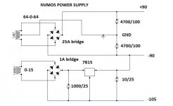
I expected this
ooh no sir? ... sorry I've made a lot of tan mile power amplifier, and the quasi NMOS as well, I just saw the design of Mr. and directly interested, so I say still new to try to master the artificial power. this afternoon I had to purchase a material to make this power. sorry for my english.....
thanks for all my ask...
warm regards
ooh no sir?
... sorry I've made a lot of tan mile power amplifier, and the quasi NMOS as well, I just saw the design of Mr. and directly interested, so I say still new to try to master the artificial power. this afternoon I had to purchase a material to make this power. sorry for my english..... thanks for all my ask...
warm regards
NVMOS
Hi Workhorse
greetings just few points to clarify after powering amp in series
very weak audio
1 100 uf cap across zener diode IN4735 is polarity of cap correct
2 positive side BC546 base to collector 15k resistor collector should get 15 volts fromjunction of 4.7K 5 WATT and 15 volts ZENER please see on pcb how
collector get supply or i am wrong
hoping you can help out i post pictures once amp comes on my supply
is 55volts dc and 70 volts
warm regards
andrew lebon
2 positive side BC546 base to collector 15k resistor collector should get 15 volts fromjunction of 4.7K 5 WATT and 15 volts ZENER please see on pcb how
collector get supply or i am wrong
Thats a mistake in ALex's pcb. Track is missing on both positive and negative side drivers, you need to connect it thru jumpers from collector of BC546 to resistor + zener midpoint. Thanxz for pointing it out, you are right Andy
.
Last edited:
1 100 uf cap across zener diode IN4735 is polarity of cap correct
Yes its wrong in Alex's Pcb, correct it please.
workhorse, what a minimum voltage for this amp and without any adjustment for the components. let say +35 0 -35 vdc.
Workhorse,how low can we go with the voltages without any change or adjustments of the components to achieve less power?
On a PSU schematics you posted seems that 4700uF caps are not enough for 400W RMS for two channels or one channel.Is that a typo or it was only a schematic to show how can we reach -105 Volts?
And what is your advice for PSU for a mono amp?
Regards,
Yugovitz
Last edited:
"seems that 4700uF caps are not enough for 400W RMS for two channels or one channel"
The values for power supply capacitance can be realistically determined by a consideration of the numerical value of W C R where W is the line frequency (377 rad/sec), C is the power supply capacitance, and R is the load resistance. An WCR value of 10 yields about 10 per cent ripple (pk.-pk. ) and a value of 100 has about two percent. Below 10, the power supply will have serious problems and values of about 100 will achieve diminishing performance returns. The minimum value then, for each of the four power supply capacitors should be about 3,000uF and the maximum about 30,00OuF. Capacitances above this value may cause diode bridge failure due to turn-on surges and are not recommended.
(http://www.passdiy.com/pdf/a40.pdf)
3,300µF x2 for one channel at 8Ω with 60hz line (3,900µF for 50hz), double for 4Ω, double again for 2Ω.
Example: Crest CA9 has a tiered supply and 120,000µF total capacitance. This is 15,000µF per channel, per tier, the 10% ripple point.
Remember, stored energy increases with the square of the voltage, so a 3,300µF cap with 100V on it stores 4x the energy that a 3,300µF cap with 50V on it stores.
radian per second = W
f*2Pi=W
377 (60hz)
314(50hz)
Last edited:
Hi Workhorse
greetings just another hiccup no 560 ohms from 2k preset to emitter of bias tr MJE340 is it omitted secondly MPSA 42 WITH 56 PF TO BE CHANGED TO BC 546 SWAP PIN around collector and emitter
warm regards
andrew lebon
Yes
@djk
any solutions...
R u new in this field ?
Hi Workhorse
greetings just another hiccup no 560 ohms from 2k preset to emitter of bias tr MJE340 is it omitted secondly MPSA 42 WITH 56 PF TO BE CHANGED TO BC 546 SWAP PIN around collector and emitter
warm regards
andrew lebon
R u talking about the Pin configurations of these transistors. Check the data of your deceives here ALLDATASHEET.COM - Datasheet search site, Datasheet search site for Electronic Components and Semiconductors and other semiconductors.
..... Hmmm
.....all this errors occur , becouse schematic was changet many times...... and I have to change PCB again and again I think it's normal to be so.
I know , no work , no mistake but I support theread this way
Alex.
.....all this errors occur , becouse schematic was changet many times...... and I have to change PCB again and again
I think it's normal to be so.I know , no work , no mistake
but I support theread this way Alex.
Attachments
"But no one seems to explain how low can we go down with the PSU voltages without changing anything in the circuit? "
Looking at the schematic in #352, you might want to keep the current through the zeners constant, otherwise it should work over a wide range of voltage.
Subtract the zener voltage from the nominal supply voltage and use ohm's law to determine the current.
Subtract the zener voltage from the new voltage and use ohm's law to determine the new resistor value (with that same current).
- Status
- This old topic is closed. If you want to reopen this topic, contact a moderator using the "Report Post" button.
- Home
- Amplifiers
- Solid State
- NVMOS amplifier