Not between, but across.
As if each resistor were a piece of wire")
I get it, we will transform resistors into jumpers
Hi Mooly,
you ruined a good joke I was just about to compare popping persistence of my amplifier to that of black knight from Monty Python, but no more so.
After I did homework you gave me, piece of wire across R529 and R530, both channels are completely silent while operating switch
Just to be sure I checked DC across C518, no problems there as well measuring 13.6V
Here is a link to that funny video anyway, I am sure you will appreciate good British humor.
Monty Python-The Black Knight - YouTube
you ruined a good joke
I was just about to compare popping persistence of my amplifier to that of black knight from Monty Python, but no more so.After I did homework you gave me, piece of wire across R529 and R530, both channels are completely silent while operating switch
Just to be sure I checked DC across C518, no problems there as well measuring 13.6V
Here is a link to that funny video anyway, I am sure you will appreciate good British humor.
Monty Python-The Black Knight - YouTube
Oh yes.... I don't give up that easily So with R530 shorted it is silent.
Just backtracking for a moment to be sure,
1. remove the jumper wires from R529 and R530 and then as we have before remove C517 and C518. It should still be silent. If so see step 4 below. If not continue
2. If the popping has returned leave C517 and C518 disconnected and then swap Q505 with Q506 and retest to see if problem has gone to other channel.
3. If still popping in same channel then swap C519 with C520 and again test.
---------------------------------------------------------------------------------------------------------------------------------------
4. If it was still silent in step 1 above then refit C517 and C518 and run those short ground wires from C505 and C506 to the correct PCB ground point as in picture in post #175. Does it still pop now ?
(I know we did some of this before but something went astray somewhere when all the voltages dissappeared so lets be sure of the results).
If it does still pop now but did not in step 1 then it appears the first two transistor stage is causing the problem.
So with R530 shorted it is silent.
Just backtracking for a moment to be sure,
1. remove the jumper wires from R529 and R530 and then as we have before remove C517 and C518. It should still be silent. If so see step 4 below. If not continue
2. If the popping has returned leave C517 and C518 disconnected and then swap Q505 with Q506 and retest to see if problem has gone to other channel.
3. If still popping in same channel then swap C519 with C520 and again test.
---------------------------------------------------------------------------------------------------------------------------------------
4. If it was still silent in step 1 above then refit C517 and C518 and run those short ground wires from C505 and C506 to the correct PCB ground point as in picture in post #175. Does it still pop now ?
(I know we did some of this before but something went astray somewhere when all the voltages dissappeared so lets be sure of the results).
If it does still pop now but did not in step 1 then it appears the first two transistor stage is causing the problem.
You certainly don't
Just a few questions, can I suggest that I first remove short from R529 and then test, just to be sure that indeed with just R530 shorted it is silent.
Step 4. Those two short ground wires from C505 and C506 they are still connected, and were connected yesterday while testing.
We had that power outage when just C506 was connected to ground via R516, not when C505 and C506 were connected to the correct PCB ground point.
So with R530 shorted it is silent.
Just backtracking for a moment to be sure,
1. remove the jumper wires from R529 and R530 and then as we have before remove C517 and C518. It should still be silent. If so see step 4 below. If not continue
2. If the popping has returned leave C517 and C518 disconnected and then swap Q505 with Q506 and retest to see if problem has gone to other channel.
3. If still popping in same channel then swap C519 with C520 and again test.
---------------------------------------------------------------------------------------------------------------------------------------
4. If it was still silent in step 1 above then refit C517 and C518 and run those short ground wires from C505 and C506 to the correct PCB ground point as in picture in post #175. Does it still pop now ?
(I know we did some of this before but something went astray somewhere when all the voltages dissappeared so lets be sure of the results).
If it does still pop now but did not in step 1 then it appears the first two transistor stage is causing the problem.
Hi Mooly,
you were right with just R530 jumpered it is silent, R529 had no influence.
I did step 1. per your instructions and it was still silent, so I jumped to step 4. and it was popping again.
Something happened while testing voltages which makes me wanna say we nailed it
, but I said it so many times already and really don't want to jinx it this time.Would you say that it is normal while touching the junction of ceramic cap C512 and resistor R522 with probe causes explosion like sound in speaker and even amp speaker relay to kick in? Touching emitters, bases and collectors of Q502 and Q504 gives me some buzz but nothing like this.
Same procedure on left combo C511 and R521 does not exhibit such behavior.
It's normal for it to make these sounds when you touch a high gain amplifier circuit.
Both channels should be similar but it's a dangerous (for the amp and speakers) thing to do. The noise will vary greatly depending on things such as whether you happen to be touching the chassis, how hard you grip the meter leads and so on. If R529 were still linked then you wouldn't hear anything from touching around Q501 and 502.
Is it correct now to say the following ?
That with R529 and R530 fitted and C517 and C518 disconnected it is silent.
And that with C517 and C518 reconnected and C505 and C506 linked to ground point on PCB it is popping in the problem channel only ?
Are we correct up to this point ?
It's normal for it to make these sounds when you touch a high gain amplifier circuit.
Both channels should be similar but it's a dangerous (for the amp and speakers) thing to do. The noise will vary greatly depending on things such as whether you happen to be touching the chassis, how hard you grip the meter leads and so on. If R529 were still linked then you wouldn't hear anything from touching around Q501 and 502.
Is it correct now to say the following ?
That with R529 and R530 fitted and C517 and C518 disconnected it is silent.
And that with C517 and C518 reconnected and C505 and C506 linked to ground point on PCB it is popping in the problem channel only ?
Are we correct up to this point ?
Hi Mooly,
sorry for not replying sooner but it was unusually busy day at work.
All of your statements above are correct.
Let me clarify on that unusual noise.
Junction of ceramic cap C512 and resistor R522 is made of one solder blob, like a solder bridge between ends of those two components, I don't know why is like that but it is the same in the left channel. My theory is this, that soldering blob because it is wide is more prone to become cold, so light pressure with probe made it temporarily conducting. When I swapped Q508 and Q507 I touched joint C511-R521 because I can see it is fresh, and probably then not knowingly I repaired popping in left channel, on the other hand this C512-R522 blob looks rather dull.
Before anything I ask your permission to attack that blob with soldering iron, after all it can do no harm.
Thanks
Marko
No problem... as and when
If any joints are suspect then definitely go over them with a hot iron.
So we are at an interesting point now.
Now let us run both channels off the known good stage like this. Keep C505 and C506 connected to ground.
Is it silent or not ?
If any joints are suspect then definitely go over them with a hot iron.
So we are at an interesting point now.
Now let us run both channels off the known good stage like this. Keep C505 and C506 connected to ground.
Is it silent or not ?
Attachments
No problem... as and when
If any joints are suspect then definitely go over them with a hot iron.
So we are at an interesting point now.
Now let us run both channels off the known good stage like this. Keep C505 and C506 connected to ground.
Is it silent or not ?
In my previous post I was referring to Q503 and Q501 not 507 and 508, but I am sure you figured that out.
What value and type for the cap in your picture should I use, I have some 220pF film and 1uF, 4,7uF, 10uF and 220uF electrolytes?
No problem... as and when
If any joints are suspect then definitely go over them with a hot iron.
So we are at an interesting point now.
Now let us run both channels off the known good stage like this. Keep C505 and C506 connected to ground.
Is it silent or not ?
It was NOT cold solder joint, one more of my theories bites the dust. I shall refrain myself in the future. I did feel kind a relieved, after a month of late night soldering I would hate the cause being something so simple.
Connecting collector of Q503 via 4.7uF cap to R532 with C518 removed and the same channel is still noisy.
How can that be, didn't we, per your scheme, just transfered left channel into the right?
Does that mean the problem is after R532?
Or should I just stop thinking and do what you tell me to do
, that is probably wisest.Never stop thinking
It's proving very elusive to pin down just what is happening here. Logic says it should have been silent on the above test yet in a way I'm not surprised it wasn't.
Another double check again... we must keep doing this to be 100% sure.
from where we are in post #193 (with cap connected to other channel and still noisy), if you again remove just the 4.7uF coupling cap it must be silent again.
Thats what we confirmed yesterday Make sure it still is.
Assuming it is OK now connect the 4.7uF cap across R530 with C518 still removed. Negative end of cap to ground of course.
Is it silent ? At this point it has got to be.
If it is, now transfer the negative end of cap to the "E7" ground point (the volume control ground on the PCB) and retest.
Is it still silent ?
It's proving very elusive to pin down just what is happening here. Logic says it should have been silent on the above test yet in a way I'm not surprised it wasn't.
Another double check again... we must keep doing this to be 100% sure.
from where we are in post #193 (with cap connected to other channel and still noisy), if you again remove just the 4.7uF coupling cap it must be silent again.
Thats what we confirmed yesterday
Make sure it still is.Assuming it is OK now connect the 4.7uF cap across R530 with C518 still removed. Negative end of cap to ground of course.
Is it silent ? At this point it has got to be.
If it is, now transfer the negative end of cap to the "E7" ground point (the volume control ground on the PCB) and retest.
Is it still silent ?
Never stop thinking
It's proving very elusive to pin down just what is happening here. Logic says it should have been silent on the above test yet in a way I'm not surprised it wasn't.
Another double check again... we must keep doing this to be 100% sure.
from where we are in post #193 (with cap connected to other channel and still noisy), if you again remove just the 4.7uF coupling cap it must be silent again.
Thats what we confirmed yesterday
Assuming it is OK now connect the 4.7uF cap across R530 with C518 still removed. Negative end of cap to ground of course.
Is it silent ? At this point it has got to be.
If it is, now transfer the negative end of cap to the "E7" ground point (the volume control ground on the PCB) and retest.
Is it still silent ?
Just to recapitulate to confirm if I understood it correctly.
With Q503 still connected to R532, I should once more disconnect C517 and confirm that it is still silent.
After that if it is, should I reconnect C517?
When connecting 4.7uF cap across R532 should the cap be connected to collector of Q503 or not?
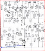
Like this. Keep C505 and C506 connected to ground as before. And C518 removed.
Connect cap as the black one shown. Then transfer just the negative lead of cap to E7 ground point as shown by blue wire.
C518 still removed, C505 and C506 still connected to ground.
Test 1. Cap across R530 with minus leg also tied to the collector of Q503=silence in both channels
Test 2. Cap across R530 with minus leg also tied to the point E7=silence in both channels
Mooly, I hope this results were wished for. I must admit this is beyond me, at this point I cant even guess where are we going, but I am willing to serve as your remote soldering hand.
They are good results.
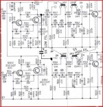
The principle of the tests is quite simple. We have established that the switch is silent with C518 removed (post #184).
C518 is a coupling cap that caries all the signal from the first stage amplifier (Q502 and Q504) to the next stage.
This is where it gets puzzling. Connecting a cap across R530 can be looked at in two ways. It both "shorts out" the input to the second stage to ground but also couples that input to the ground point in such a way that if there were any noise/unwanted signal etc present (on that ground) it would pass it to the amplifier and we would hear it.
And we don't, it's silent.
When we moved the cap along the ground it was still silent as it should be.
The puzzle is why the noise returns when C518 is refitted. Is C518 coupling an unwanted signal ? Well we cross coupled the input stages to to the good channel to try and prove or eliminate that as a cause and the noise was still there. That's where this gets strange and a bit contradictory in what seems to be happening.
Thats all correct I think up to this point
So where do we go from here...
There is one more test we are going to do now. With C517 and C518 fitted and C505/6 connected to the E7 ground remove Q502 and see if the noise is there. Doing that will cause the voltage on Q504 collector to fall to around 6 volts or so.
Big question... is it still noisy ? If it is, then pull out Q504 as well and retest.
They are good results.
The principle of the tests is quite simple. We have established that the switch is silent with C518 removed (post #184).
C518 is a coupling cap that caries all the signal from the first stage amplifier (Q502 and Q504) to the next stage.
This is where it gets puzzling. Connecting a cap across R530 can be looked at in two ways. It both "shorts out" the input to the second stage to ground but also couples that input to the ground point in such a way that if there were any noise/unwanted signal etc present (on that ground) it would pass it to the amplifier and we would hear it.
And we don't, it's silent.
When we moved the cap along the ground it was still silent as it should be.
The puzzle is why the noise returns when C518 is refitted. Is C518 coupling an unwanted signal ? Well we cross coupled the input stages to to the good channel to try and prove or eliminate that as a cause and the noise was still there. That's where this gets strange and a bit contradictory in what seems to be happening.
Thats all correct I think up to this point
So where do we go from here...
There is one more test we are going to do now. With C517 and C518 fitted and C505/6 connected to the E7 ground remove Q502 and see if the noise is there. Doing that will cause the voltage on Q504 collector to fall to around 6 volts or so.
Big question... is it still noisy ? If it is, then pull out Q504 as well and retest.
Hi Mooly,
And thank you for your kind explanation.
I am afraid I have more info for your brain cells, power outage again.
I forgot to measure DC voltage on Q504 yesterday while testing, so I decided to do that this morning.
So in this setup: C518 still removed, C505 and C506 still connected to ground, cap across R530 with minus leg also tied to the collector of Q503 I am getting following voltages on collectors:
Q504 12.33V
Q502 3.36V
Q503 1.5mV
Q501 0.6V
Interesting, don't you think?
It's no problem.
Lets analyse what you are saying for these DC faults...
C518 removed... yes and that is OK
C505 and C506 to ground... make sure it is the left hand ends of cap on circuit that go to ground. That is points 11 and 12 on the diagram.
" cap across R530 with minus leg also tied to the collector of Q503 "
I think you have an incorrect connection somewhere here. A cap across R530 will not alter the DC conditions.
"Minus leg tied to collector".... Not quite sure what you have done here. The collector is most positive point around where we are working. If you have connected Q503 collector to the minus leg on this cap then you have shorted out the transistor to ground. It won't damage anything though. That would explain the readings if that is what you have done.
Switch off and measure on ohms from Q503 collector to ground. Is it reading short circuit ?
- Status
- This old topic is closed. If you want to reopen this topic, contact a moderator using the "Report Post" button.
- Home
- Amplifiers
- Solid State
- Help with DC on volume pot