Thanks lorriman. I have to check out the Fostexs. It have never occured to me that one could build headphones yourself...
Brgds
Well, it's not quite building; just a mod. A fairly easy one also.
My (untested) version of aux O2 power
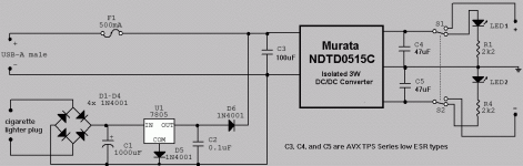
This is the parts values and schematic for implementing auxiliary power for the O2 using a USB port or a 12VDC lighter socket. I'm deciding on a suitable case still and the circuit hasn't been built. Its main purpose is to recharge the O2's batteries, but the converter can output about +/-100mA. It could power some headphones.
It's nothing spectacular or out of the ordinary. I just want it to work, and I think it will. Corrections will be most appreciated.
The switched LEDs are to keep a load on the converter, and provide a visual indication to plug-unplug without a live TRS plug. TRS seems the most practical connection. The socket is on the back panel (there's plenty of room in the B2 case above R1 & R2) using a grommet insulator.
Attachments
This is the parts values and schematic for implementing auxiliary power for the O2 using a USB port or a 12VDC lighter socket. I'm deciding on a suitable case still and the circuit hasn't been built. Its main purpose is to recharge the O2's batteries, but the converter can output about +/-100mA. It could power some headphones.
It's nothing spectacular or out of the ordinary. I just want it to work, and I think it will. Corrections will be most appreciated.
The switched LEDs are to keep a load on the converter, and provide a visual indication to plug-unplug without a live TRS plug. TRS seems the most practical connection. The socket is on the back panel (there's plenty of room in the B2 case above R1 & R2) using a grommet insulator.
This is marvellous!!
@sofaspud I built very close to the exact thing to power Tangent's Mint circuit that I use as a pre amp for my car audio system. I don't use the USB input tho. Works well and does a fine job of isolating and regulating the car's power system from the pre amp circuit, not to mention the =/- power output!
Last edited:
UK - Enclosures
If anyone's interested, CPC in the UK are running a promotion at present, offering free shipping on orders over £10 (excl. VAT) - usually, you have to order £40 worth of stuff to qualify for free shipping. Anyhow, this offer runs until 23 Jan - and they sell the O2 enclosures, e.g. BOX ENCLOSURES|B2-080BK|ALUMINIUM INSTRUMENT HOUSING | CPC
http://cpc.farnell.com/box-enclosures/b2-080bk/aluminium-instrument-housing/dp/EN81735
@Lorriman - thanks for the heads up on the Superlux HD681 - currently £19.49 from Amazon http://www.amazon.co.uk/Superlux-HD...IPYI/ref=sr_1_1?ie=UTF8&qid=1327092021&sr=8-1
lots of interesting reviews, got to be worth a try, so I've ordered a pair.
lots of interesting reviews, got to be worth a try, so I've ordered a pair.
Hey guys I'd figure I would just post in this thread as well. I have a 5 page thread about how I just built two Objective 2 amps and neither will work on AC power. They both work just fine with batteries installed but not on AC power. Please help me! It must be something I am doing wrong or have a bad part. I've tried various tests with no luck!
The main purpose of the bridge rectifier is to make that input polarity insensitive. + will be + and - will be - no matter how the DC is connected. I put a large value cap across it, so the lighter plug input is quite versatile. It can accept AC also, up to about 24VAC peak (higher voltages are possible even, but then the reverse voltage seen by the diodes and the power dissipated by the regulator has to be considered).
D5 raises the output of the 7805 by a diode drop. That offsets the D6 drop (D6 blocks DC from entering the regulator output). In practical use, D6 will likely have a higher voltage drop than D5, so perhaps two diodes at the D5 position would be an improvement. Or it may not matter much; the DC-DC converter is rated at 4.5 to 9V input.
It should be mentioned also that the +15VDC output connects to the cathode of D3 on the O2 schematic. The -15VDC connects to the anode of D4 on the O2 schematic.
Last edited:
Hey guys. I'm starting the build of my O2's and while starting with the resistors I got to R3 & R7 (274 ohm 1%) but before I solder them I always measure them (using a Fluke 75) and all 8 measured at ~345 ohm. The color code is correct for 274. I found it's a bit off spec. Do you think it would be a problem to use them in R3 & R7 in the positive input of the 2068 opamp? (I do not care for R19 & R23 Gain of 6.5). Thanks
Last edited:
Hi.
I'm back to let you all know about the problem i had with my O2 not running on AC power.
With agdr's help, we managed to narrow the issue down to the U5 Regulator. So, before having a new one to trade with the supposedly dead regulator, i decided to heat the iron and remake the soldering. Guess what? It's working like a charm on AC now. I swear that i don't understand how it's working, because the solder points seemed good the first time. Anyway, it's working on AC, and that's all that counts.
But, and because i'm (not) a lucky guy, i am facing a different problem now.
I've bought a pair of Philips 9v rechargeable batteries to go with the O2. The thing is, they last about 1 hour before the amp starts turning itself on and off repeatedly, a sign that the batteries are nearly dead and need recharging.
I'll try to run 3 or 4 more charge cycles to them before trading them with something else.
raspunsen - hey that is good news! Just curious - was it reheating the joints one of those 6 parts above that solved it-
...or was it some other joint? Hard to tell sometimes visually with solder joints. Reheating suspect areas is never a bad idea.
Another suggestion, after helping jschristian44 with his issue. It couldn't hurt to solder the banded lead of D3 on the top of the PCB to that square pad around it. Turns out that square pad is a via through-hole. Soldering the top would eliminate any chance of the through-hole having issues and the solder joint on the bottom not conducting up to the top. Just on the banded end of D3, the other diodes and leads don't need it.
As for the low battery issue, have you made the two resistor modifications that RocketScientist posted in the directions? The 2.7meg resistor is now 1.5meg, as a I recall, and another resistor was changed to 33K if I'm remembering correctly. Those helped with that low battery on/off cycling issue. I think the discussion at the time between RocketScientist and people with the problem said that some batteries had the issue worse than others. Trying a different brand would be worthwhile.
raspunsen - yep, your negative power supply is good but your positive power supply is dead.
Double check the positions of your D1, D3, C2, C4, R1 and regulator U5 match up with the symbols on the PC board, that they are turned the right way.
...... If the positions are OK and no bridges then try re-heating the solder joints on those 6 parts with your iron.
...or was it some other joint? Hard to tell sometimes visually with solder joints. Reheating suspect areas is never a bad idea.
Another suggestion, after helping jschristian44 with his issue. It couldn't hurt to solder the banded lead of D3 on the top of the PCB to that square pad around it. Turns out that square pad is a via through-hole. Soldering the top would eliminate any chance of the through-hole having issues and the solder joint on the bottom not conducting up to the top. Just on the banded end of D3, the other diodes and leads don't need it.
As for the low battery issue, have you made the two resistor modifications that RocketScientist posted in the directions? The 2.7meg resistor is now 1.5meg, as a I recall, and another resistor was changed to 33K if I'm remembering correctly. Those helped with that low battery on/off cycling issue. I think the discussion at the time between RocketScientist and people with the problem said that some batteries had the issue worse than others. Trying a different brand would be worthwhile.
Last edited:
Seems like you have given me the answer to my problem and i forgot to check it at the time... Shame on me. Guess i just assumed U5 was dead because the solder joints seemed ok.
I just heated the 3 joints of U5 and it's working fine now.
I still have the old resistors. I don't mind having this behaviour, it's a sign i need to recharge it. It's just that 1 hour seems like too short. I was expecting more.
Edit: @jschristian44: My batteries are Philips. Not the cheap kind...
I just heated the 3 joints of U5 and it's working fine now.
I still have the old resistors. I don't mind having this behaviour, it's a sign i need to recharge it. It's just that 1 hour seems like too short. I was expecting more.
Edit: @jschristian44: My batteries are Philips. Not the cheap kind...
Last edited:
Hey guys. I'm starting the build of my O2's and while starting with the resistors I got to R3 & R7 (274 ohm 1%) but before I solder them I always measure them (using a Fluke 75) and all 8 measured at ~345 ohm. The color code is correct for 274. I found it's a bit off spec. Do you think it would be a problem to use them in R3 & R7 in the positive input of the 2068 opamp? (I do not care for R19 & R23 Gain of 6.5). Thanks
Sorry guys, I found the problem. The adaptor clip on my Fluke was the problem. Funny that it was measuring ok with other Resistors. My bad


raspunsen - definitely try a different brand of batteries. Not even so much bad batteries as just different. The different batteries have different internal properties. The issue causing the on/off is re-charge behavior of the batteries. After the load if removed (the power management circuit turns off) some batteries tend to "recharge" back up to a higher voltage on their own, which then turns the power management circuit back on. A different brand may not do that as much.
- Home
- Amplifiers
- Headphone Systems
- The Objective2 (O2) Headphone Amp DIY Project