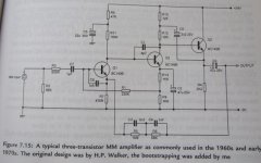
So I finally find again some time to toy with a minimalistic phono pre and like the simplicity of the bootstrapped variant of the H.P. Walker phono stage presented by Douglas Self in his book on small signal audio design (p185). I attach the original schematic as it is to my knowledge not available online elsewhere (mods please let me know if that is copyright troublesome).
Punching my own variant of it into SPICE, I find the RIAA equalization (C3/C4/R5/R6) of the circuit (the same happens for the original unmodified circuit) is lacking precision, not to say it is far off at 20 Hz with 6dB or so.
Calculating the RIAA time constants* the values are indeed far off:
C3xR5=5940us (should be 3180us)
C4xR6=68us (should be 75us)
(R5||R6)x(C3+C4)=281.7us (should be 318us)
Curiously the same values are also used in the 2-transistor variant on the page before.
Using adapted values like 1nF/3.6nF/75k/883k bring back the accuracy, both in the equations as well as in simulation; (as these values are not available, one would select more suitable real-life values like 820+10pF/3nF/89.9k/1.06M or so).
As my prototype will be finished only in a few weeks, I can't check the actual circuit yet.
I can't see something wrong with my calculations or understanding of the circuit, but as I respect Mr. Self very well, I wonder if I'm missing something?
Hannes
*nice little exercise, see equations for the inverting RIAA-network at
Website of Wayne Stegall - Phono Equalization Calculations
Attachments
Have you seen the classic RIAA paper by Lipschitz? In many RIAA networks, few of the CR time constants directly equal the RIAA values, as the components interact. You can get into trouble by comparing a (possibly wrong) RIAA network with a (possibly wrong) inverse RIAA network. Much better to compare simulated/measured response with a proper calculation, as the calculation will be free of assumptions about network interactions.
Two things:
1. This is presented as a "typical" circuit from the '60s, and indeed it is. RIAA conformance was somewhat loose, and this EQ network uses standard R and C values, compromising absolute accuracy. That's good for cost and manufacturability, though.
2. The time constants are more complicated than that- you treat them as if they don't interact, but in fact they do. See Stanley Lipshitz's definitive paper in JAES (and a simpler version in Audio Amateur) about how to do those calculations correctly.
edit- Crosspost with DF96, sorry.
Thanks for pointing me to the interaction problem and the reference to the Lipshitz-Paper! I will see whether I can get access to it.
Any case, it appears strange to me that also the simulation does not give the correct results; I would assume interacting impedances should be treated properly in SPICE. Otherwise SPICE would be pretty pointless for calculating filter responses.
Hannes
Any case, it appears strange to me that also the simulation does not give the correct results; I would assume interacting impedances should be treated properly in SPICE. Otherwise SPICE would be pretty pointless for calculating filter responses.
Hannes
Last edited:
Spice will usually correctly simulate what you give it. Are you comparing gain with the formula, or inserting an inverse network with perhaps the same mistakes as the network you are testing? Quite a lot of published/commercial RIAA preamps get it wrong, so I would not be in the least bit surprised if some inverse networks are wrong too.
Last edited:
I'm simply checking the -20dB at 20Hz versus 1kHz and +20dB at 20kHz relative to the amplitude at 1kHz. That simple property is not fulfilled.
Meantime I was lucky and could obtain the Lipshitz-paper; it does not appear to do so much different, it seems that particularly the resistor/cap ratios change significantly, while the time constants are still calculated in the same way (for this particular network).
We'll see, I'll give it a good read tomorrow")
Meantime I was lucky and could obtain the Lipshitz-paper; it does not appear to do so much different, it seems that particularly the resistor/cap ratios change significantly, while the time constants are still calculated in the same way (for this particular network).
We'll see, I'll give it a good read tomorrow
Many early and/or discrete designs obtain the 3180us LF shelf from a combination of network values and 'insufficient' loop gain i.e. the network compensates for the lack of gain. This means that the circuit will be sensitive to the current gain of Q2, as that helps set the open loop voltage gain. Self's output bootstrap will have changed things a little too. What degree of accuracy does he claim for it? This complication does not appear with an op-amp active circuit or a passive circuit.
SY and DF96 are absolutely correct about the time constants. The network components interact so you cannot use simple R.C time constants. The classic paper on the subject is by Lipshitz and on my website I have a write up and an RIAA calculator based on his equations.
Lipshitz also addresses the issues arising when using feedback RIAA amplifiers where the loop gain is insufficient, which for the most part is what you will get with simple 2 and 3 transistor circuits.
Lipshitz also addresses the issues arising when using feedback RIAA amplifiers where the loop gain is insufficient, which for the most part is what you will get with simple 2 and 3 transistor circuits.
Last edited:
The network components interact
Lipshitz notes a 8-18% influence due to the interaction, not the 6dB that I see in simulation.
By the way, thanks for the hint to your article. I know it already and find it an interesting writeup! However, I find it irritating that your spreadsheet claims to work with R3=0, but always displays non-zero (and even negative) values for R3, which is inconsistent.
the network compensates for the lack of gain.
That is indeed a very interesting point, that I unfortunately cannot investigate as I don't know the originally used part BC149B. Was there really so much gain improvement for small signal bjts since the late 70ies? By the way, D. Self does not mention anything with respect to RIAA accuracy for this specific circuit (he mentions +1.6dB@20Hz for the simpler version without the follower though).
The Lipshitz article is really great to read and full of interesting points.
After all it seems, that the RIAA of the posted circuit is indeed not correct. I didn't calculate yet the finite open loop gain corrected constants, but simulation said right from the beginning the RIAA was inaccurate and the Lipshitz-values immediately bring the accuracy back. Still I might be wrong, and prototyping it will give the definitive reply in any case.
As even Self's version of the little circuit dates back to November '76 (almost 3 years before Lipshitz' paper) and he likely soon turned to the NE5534 based preamp (published '83), this error might have gone unnoticed. Especially as it appears to me after his NE5534 pre he never looked back at the original circuit.
These phono preamps are really fascinating little beasts
Hannes
Last edited:
"By the way, thanks for the hint to your article. I know it already and find it an interesting writeup! However, I find it irritating that your spreadsheet claims to work with R3=0, but always displays non-zero (and even negative) values for R3, which is inconsistent."
Thaks for raising that - it's a valid point. I don't know that I can neccessarily change it, but I may put a note on the spread sheet to highlight the fact that this may happen, and you just need to ignore it.
Thaks for raising that - it's a valid point. I don't know that I can neccessarily change it, but I may put a note on the spread sheet to highlight the fact that this may happen, and you just need to ignore it.
IMO, Hagerman has some good stuff on inverse networks here. One thing I've found is that measuring RIAA accuracy directly using signals and meters if fraught with difficulty. The dynamic range required is large and if the meter switches ranges you lose accuracy. The best way would be with a ratio transformer, but not many have those hanging about in the lab. Thus, a carefully measured inverse network is best.
What about a sound card followed by an attenuator network to generate the inverse curve? I've done (and do) embedded programming, but nothing on the PC but I think this would be an absolute cinch with VB - generate and measure all out of one card. Maybe there's already some software out there, and if not, we should suggest it to RightMark.
If one hooks the circuit up to a pc, one can always do a frequency sweep and compare that to a calculated RIAA response (created in Excel with the measured gain at 1kHz). The comparison is not real-time, but that's usually not necessary as fine-tuning the RIAA is not a matter of changing single component values (as Lipshitz discusses at length ;-) ).
Thanks for the link to inverse RIAAs, might come handy though.
Well, if you set R3 to zero, it has to be zero all the time. I don't see why a value for R3 is calculated at all. If you look e.g. at Table 3a, you see that R3 and R0 always show up together. Setting R3 to zero, only R0 remains in the equations, so there remains in fact no relation one could use to calculate R3.
Thanks for the link to inverse RIAAs, might come handy though.
I don't know that I can neccessarily change it
Well, if you set R3 to zero, it has to be zero all the time. I don't see why a value for R3 is calculated at all. If you look e.g. at Table 3a, you see that R3 and R0 always show up together. Setting R3 to zero, only R0 remains in the equations, so there remains in fact no relation one could use to calculate R3.
Last edited:
Bonsai, that seems like a reasonable approach, assuming the s/n ratio is good enough and the attenuator is chosen wisely. I bring up the issue because people get interested in fractional dB errors, and the measurement isn't trivial given the combination of small signal levels, dynamic range and frequency range.
What about a sound card followed by an attenuator network to generate the inverse curve? I've done (and do) embedded programming, but nothing on the PC but I think this would be an absolute cinch with VB - generate and measure all out of one card. Maybe there's already some software out there, and if not, we should suggest it to RightMark.
I use an inverse RIAA 1/10th octave multitone signal and a sound card which you can average as long as you want. SoX will do it all for free.
Last edited:
Sure, that's certainly most practical!
I guess Scott means Sound eXchange, a powerfull command-line tool
SoX - Sound eXchange | HomePage
I guess Scott means Sound eXchange, a powerfull command-line tool
SoX - Sound eXchange | HomePage
The open loop transfer function of Self's circuit will influence the component values required in the feedback network. In the case of an op amp the open loop gain is high enough for it to be ignored, but not here.
You can try a single dominant pole approximation of the open loop transfer function with the actual LF gain and the actual dominant pole, and calculate the required feedback values accordingly. I did that many years ago, but without taking the open loop gain into account I just could not get an accurate RIAA curve, especially at the HF end of the RIAA CURVE IIRC. By taking the open loop transfer function into account, the required target transfer function was met satisfactorily. It might have required an extra component in the feedback network, I can't remember exactly
It is perhaps easier to simulate in Spice until you get the target curve right.
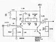
While we're on the topic of simple phono sections, here's the circuit used in the old Ace Audio preamp from around '74. It sounded quite good, though I've no idea how accurate it is. They also had a line stage, but eliminated it for the "zero distortion" version. From my archives.
Attachments
- Status
- This old topic is closed. If you want to reopen this topic, contact a moderator using the "Report Post" button.
- Home
- Source & Line
- Analogue Source
- Error in D. Self-Riaa?