Dynavector and any of the "passive" straight line tracking arms with have very different horizontal-vertical resonances. The dampers supporting the stylus do decay. They are rubber or similar and smog can do them in fast. If ity were kept in an inert environment (Krypton?) the cartridge may not have aged. Its not uncommon to see the dampers collapse after a few hours of play.
I would prefer the Flac file as well. Less romantic perhaps, but much closer to the original intent of the producer.
I would prefer the Flac file as well. Less romantic perhaps, but much closer to the original intent of the producer.
I'm assuming the primary component in the LF resonance is the stylus compliance against the effective tonearm mass. I guess if the vertical and horizontal compliance of the cartridge are the same (why would they be different?), then maybe vertical and lateral arm-cartridge resonance may be the same.
Bob, if you think about it it would be hard to decouple V and H resonances by a large amount, especially considering the resonant frequencies vary as the square-root of the product of mass and compliance.
Demian brings up a very important exception, straight line trackers can have very different H/V mechanics.
Last edited:
Scott here are some measurements I made of those big fets compared to the Toshibas. Measured at 10 Volts on the drain about 4 mA. The circuit is very similar to the one you did but biased without the Vishay parts. After CES I want to look a little closer using my HP signal analyzer now that my HPIB is running.
Attachments
 I did add some nice reference resistors that are jumper selectable though. Somebody has to be the smartest guy around and I know it's not me.
Scott here are some measurements I made of those big fets compared to the Toshibas. Measured at 10 Volts on the drain about 4 mA. The circuit is very similar to the one you did but biased without the Vishay parts. After CES I want to look a little closer using my HP signal analyzer now that my HPIB is running.
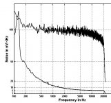
I'm a little confused by the plots. They look a little different than I would expect. usually there is a flat noise floor to some lower frequency wher the 1/f curve start and it rises below. A HF rolloff is usually indicative of the amp circuit running out of gain, not the noise falling.
Calibration with a 600K resistor is a good trick, until the input C of the part rolls off the noise from the resistor. With the 200 pF input C that could happen at a pretty low frequency.
You only need a baseline to set a reference, the resistor with no DC current will be flat down to very low frequency. If it starts to roll off at even a few kHz just take a reading at 500Hz or whatever. You would need to verify that there was no generation recombination noise contributing to these plots.
A quick example, it's pretty easy to eyeball the flat portion of the noise spectrum of the circuit with resistor added (top plot).
Wayne, initially I was thinking DIY Quantek traceable calibration etc. In reality some knowledge and savy in the user goes a long way.
Wayne, initially I was thinking DIY Quantek traceable calibration etc. In reality some knowledge and savy in the user goes a long way.
Attachments
Thanks I might have been overly ambitious in picking 604K, some of the feedback I got was that some folks were flumuxed by the concept of un-root sum squaring two noises so I picked a resistor that would totally dominate. I expect those Interfet parts to seriously roll off due to Miller effect. It's hard to present things so they are unambiguous to any level of reader.
 Gentlemen. No need to quote the entire post just above yours. I have fixed the over-quotes.
Please see here: http://www.diyaudio.com/forums/everything-else/203174-real-apology-andrew-t.html
And this is why the concept of damping the mechanical system with a loading resistor is a myth. The interesting question is how much the nonlinearity of the magnetics gets involved when a cartridge is loaded such that some current passes.
Hm. I think, it is not a myth.
But it works only with a groundfree and balanced input at the MC Stage.
And it depends on the source resistance. Very low resistance there suppress the effect and extrem low noise stages.
With 20 - 50 Ohms there is a lot more headroom.
Standard single ended inputs do not allow to make a real difference between current matching and voltage matching by resistance, since the resistor is parallel to the MC and ground.
Groundless can be done with transformers also.
Magnets are another thing. Many modern systems avoid pole shoes (Marketing crap abouth nonlinearity), thus big loss and low ouput.
No cone speaker maker would avoid poleshoes, since they want the field were it is needed and the fieldlinearity can be better controlled.
The siliconbased rubber dampers are almost aging proof, allow hard suspension and thus they do not damp everything away, what is generated bycrazy ringing cantilevers. This gives headroom for damping by resistor.
Strong magnets and pole shoes allow the use of higher source impedance and reach thus enough output to enable impedance matching .
Hm. I think, it is not a myth.
But it works only with a groundfree and balanced input at the MC Stage.
And it depends on the source resistance. Very low resistance there suppress the effect and need extrem low noise stages.
With 20 - 50 Ohms there is a lot more headroom.
Standard single ended inputs do not allow to make a real difference between current matching and voltage matching by resistance, since the resistor is parallel to the MC and goes to the ground.
Groundless can be done with transformers also.
Magnets are another thing. Many modern systems avoid pole shoes (Marketing crap abouth nonlinearity), thus big loss and low ouput.
No cone speaker maker would avoid poleshoes, since they want the field were it is needed and the fieldlinearity and strenght can be better controlled.
The siliconbased rubber dampers are almost aging proof, allow hard suspension and thus they do not damp everything away, what is generated by crazy ringing cantilevers. This gives headroom for damping by resistor.
Strong magnets and pole shoes allow the use of higher source impedance and reach thus enough output to enable impedance matching .
It's hard to present things so they are unambiguous to any level of reader.
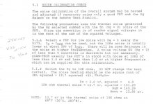
I forgot the most important thing, this eliminates the need to compute the noise BW of your filter bank. Even with the FFT you neeed to take into account the number of bins and the windowing, but now all that factors out by having a reference based on first principles right at the input. The temperature correction is so small that I usually ignore it (root(4KTR)) since temp is in Kelvins its ~300 degrees plus minus 5 or 10 degrees difference in room temperature.
Last edited:
Hm. I think, it is not a myth.
But it works only with a groundfree and balanced input at the MC Stage.
And it depends on the source resistance. Very low resistance there suppress the effect and extrem low noise stages.
With 20 - 50 Ohms there is a lot more headroom.
.
Possible confusion here, even with one side grounded all the coil current is delivered to the source resistor. We are talking about mechanical damping by this current working back magnetically through the cartridge motor system. I also don't see folks thinking this through, higher frequency tip mass, etc. resonances are even more decoupled from the motor assembly.
Moving coil cartridge damping
I did this something like 30 years ago so the details are lost in the mists of time but if you take the ratio of energy in to energy out its well less than 1%. In that case even a short can't make a huge change in the mechanical motion at the coils. And the stylus has a lot of leverage on the coils.
I did this something like 30 years ago so the details are lost in the mists of time but if you take the ratio of energy in to energy out its well less than 1%. In that case even a short can't make a huge change in the mechanical motion at the coils. And the stylus has a lot of leverage on the coils.
Moving coil cartridge damping
I did this something like 30 years ago so the details are lost in the mists of time but if you take the ratio of energy in to energy out its well less than 1%. In that case even a short can't make a huge change in the mechanical motion at the coils. And the stylus has a lot of leverage on the coils.
I also don't think there is much counter-EMF-based mechanical damping in a MM cartridge, even if it were loaded with a low resistance. I did an experiment to check this, but I completely admit that I could be wrong. I hypothesized that if the electromechanical coupling was strong enough to create electromechanical damping, then a carefully-done impedance plot of the cartridge alone would show some anomaly at the cantilever resonance frequency.
I did this, using a 3580A spectrum analyzer in impedance measuring mode and found no hint of a cantilever resonance, on two MM cartridges where I "knew" the cantilever resonances were about 19 kHz and 28 kHz, respectively. The electrical connections were directly to the cartidge, with no external capacitance (the capacitance of the spectrum analyzer input was mitigated by a resistive voltage divider).
The presumed cantilever resonance of these cartridges was inferred by playing a test record with a squarewave on it when the cartridge was heavily resistively loaded so that any ringing could not be attributed to electrical cartridge resonance.
Cheers,
Bob
If the resistor is not grounded, just parallel to coil, in real balanced mode, and make the resistor the same value like the source coil, so we have current feedback ( which can damp or not?.
If a nearly shortcut an electric motor ( bicycle dynamo) with a power lamp bulb, then the dynamo give much more mechanical resistance than in open loop.
Tip , cantilever, coil and Vinylproperties result in a resonance around 20 Khz. Well executed, this is self damped.
The resistor groundfree can reall damp the whole system and shift the Fres somewhat, similar to capacity with MMs. The damping rubber in the MCs is mainly deciding the sound of the cartdridge and this way we have a limited influence with the resistor.
Parallel resistors to ground mainly lowers the the output level by voltage feedback and thus the Fres is at the same place but lesser strong, but we need more amplification. We can hear the sound gets duller with lower ohms and brighter with higher ohms.
Moving coil cartridge damping
Bohumil Sykora developed a circuit with active damping called "Actidamp" and several phono preamps like Actidamp MkII - MkIV types were produced.
- Status
- Not open for further replies.
- Home
- Member Areas
- The Lounge
- John Curl's Blowtorch preamplifier part II