Those voltages look OK about 5 mA through one fet. More fets will bring R9 voltage down. Maybe just add one at a time.
Cheers Wayne , I'll try that in the morning . Have a nice weekend
")
Rich
I finally received my metalwork. The square holes for the PEM are always a hold up for me.
Anyway, here is a peek --
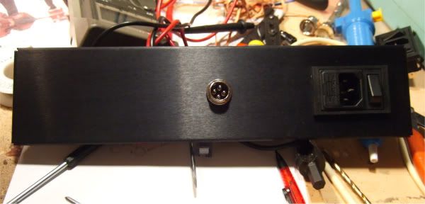
To those of you looking at this photo and thinking that it makes much more sense to put the umbilical plug on the other side, you are absolutely correct. The machine shop drilled it upside down. Oh well, it's not that big of a deal.
Anyway, here is a peek --
To those of you looking at this photo and thinking that it makes much more sense to put the umbilical plug on the other side, you are absolutely correct. The machine shop drilled it upside down.
Oh well, it's not that big of a deal.
Very nice work. Please tell us when it's completed
I use the same power cons. Would you mind telling where I can find them on an online catalog, ot the name they have? I've bought mine to the local shop, but it closed definitely, so I would upgrade mine with a dual mono external supply ... There is a 7 pin version too, right ? That one is the 4 pin version.
Best,
nAr
Best,
nAr
Nar - The connector is called a microphone jack, and I have only ever seen them in 4 and 5 pin versions. They are available at Radio Shack here in the US.
4-Pin Panel Mount Microphone Audio Jack - RadioShack.com
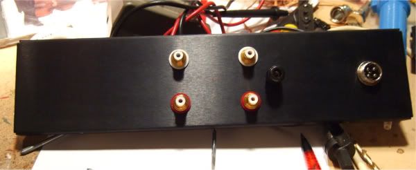
I need to buy another, I only have one, and swapped it between the panels for the top photos...
4-Pin Panel Mount Microphone Audio Jack - RadioShack.com
I need to buy another, I only have one, and swapped it between the panels for the top photos...
Nar - The connector is called a microphone jack, and I have only ever seen them in 4 and 5 pin versions. They are available at Radio Shack here in the US.
4-Pin Panel Mount Microphone Audio Jack - RadioShack.com
I need to buy another, I only have one, and swapped it between the panels for the top photos...
Thanks for the info 6L6
Best,
nAr
XLR connectors would be very good in this application, and the original design only needs 3 pins from the PSU to the RIAA chassis.
An entirely dual-mono PSU would be nice to make. I am considering a fully discrete regulator for this project, but only once I get the stock circuitry up and running. (And honestly, if I can get everything dead quiet, I am sure that I will not mess with it...)
An entirely dual-mono PSU would be nice to make. I am considering a fully discrete regulator for this project, but only once I get the stock circuitry up and running. (And honestly, if I can get everything dead quiet, I am sure that I will not mess with it...)
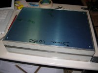
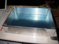
I took advantage of the heat wave in London and did a little bit of case work today ... This is the RIAA box , PSU is the same ,but slightly smaller .
B1 enclosure will be exactly the same . I hope to get everything anodised once its finished .
Its a very simple build with the correct tools .
B1 enclosure will be exactly the same . I hope to get everything anodised once its finished .
Its a very simple build with the correct tools .
Attachments
Q3
Hello all
First, many thanks to Wayne for making the Pearl 2 design and pcbs available to the DIY community, and thanks to all of you for writing in this thread! This is awesome!
I too am in the process of building a Pearl 2 and need some help. The boards are populated and troubleshooting has begun...
Supplies look good at +/- 24V. Q1 is doing its job dropping front-end supply to 19.82V. I measure about 75 mV across each one of R21, R22, R23 and R24. Therefore the total draw of the four jfets Q6, Q7, Q8 and Q9 combined is four times 7.4 mA = 29 mA, and the voltage drop across R9 is 499 ohms times 29 mA = 14.57V. This brings the emitter of Q3 to 5.24 V (19.82 less 14.57). The base of Q3 is at 5.9V. The collector of Q3 is at 5.20 V. There is only about 37 mV between the collector and emitter of Q3. Are these values within acceptable range or do I need to make adjustments? Should I reduce R9 to increase Vce of Q3? Remove one of the jfets?
Pierre
XLR connectors would be very good in this application, and the original design only needs 3 pins from the PSU to the RIAA chassis.
An entirely dual-mono PSU would be nice to make. I am considering a fully discrete regulator for this project, but only once I get the stock circuitry up and running. (And honestly, if I can get everything dead quiet, I am sure that I will not mess with it...)
That I intend. I will build UGS style regs. Got the boards. Still need the case ( hifi2000 small ) to contain dual PSU. Yes, an XLR connector would also do. I still need 7 pins because I run each ground - V+ - V- and separate Earth.
Best,
nAr
I still need 7 pins because I run each ground - V+ - V- and separate Earth.
When I went to the store and bought the connector, they had an 8-pin version!! However, I didn't see any of the chassis mount jacks, only the cable mount... It's worth looking again, as I was searching for the 4-pin.
I took advantage of the heat wave in London and did a little bit of case work today ...
Its a very simple build with the correct tools .
Those look fantastic!
Yes, the right tools are a must, I have always thought that there is no chassis I couldn't make with a 6-axis CNC mill in my basement...
You can change values to get more Vce on Q3. It is current dependent on the fets. I haven't found a big measured difference if any but prefer proper bias.
Many thanks, Wayne. This is just what I needed! The fets did put Q3 in saturation mode. After lowering R9 from 499 to 333 ohms I now have 9.6V at the collector, 9V at the base, and 8.4V at the emitter. Vc > Vb > Ve and Q3 is forward biased. All is good.
I'm listening to it right now. Speechless ... musical bliss

Pierre
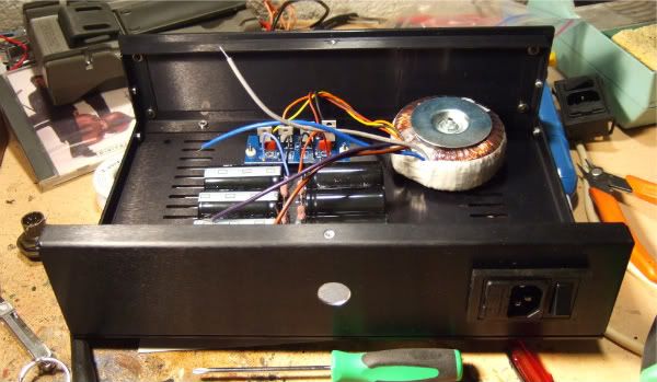
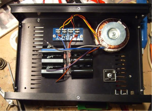
My project is coming along nicely, I powered up the PSU today, It didn't blow up! (Always good...)
No load voltage is still a bit high at + and - 43v, I'm not sure if it will get below 40v at the regulator input under load. (Remember, there is one more RC filter before the regulator.) Some bigger resistors might need to be used, or perhaps just adding more of the 10ohm in series to make 20ohm...
Photos to be posted later.
Many thanks, Wayne. This is just what I needed! The fets did put Q3 in saturation mode. After lowering R9 from 499 to 333 ohms I now have 9.6V at the collector, 9V at the base, and 8.4V at the emitter. Vc > Vb > Ve and Q3 is forward biased. All is good.
I'm listening to it right now. Speechless ... musical bliss
Pierre
Oh so is that the same problem that Rich had ?
So I understand better, if IDSS of the K170BLs are a little high then Q3 gets "on his knees",
so an adjustment is needed via R9 to get about 9 to 10V on jfet drains.
Ok, got it
Best,
nAr
- Home
- Amplifiers
- Pass Labs
- Pearl Two