Wavebourn, why are you making a reference to 'vacuum'? The only vacuum is in the tube. This issue is how to locally transfer heat out of the region around the compact array of tubes, in a manner where hot-spots don't occur. Forced air, perhaps using baffles to even out the flow in certain areas depending on how the air enters and exits, is to my mind the simplest practical solution, but you don't seem to want to entertain the option?
The valve glass exterior surface is large and per se able to cope with free-air convection. IR radiation from one valve that transfers to the outside of another valve, and hence heats its surface up more, would be alleviated or more than counteracted by the improved convective heat transfer.
The valve glass exterior surface is large and per se able to cope with free-air convection. IR radiation from one valve that transfers to the outside of another valve, and hence heats its surface up more, would be alleviated or more than counteracted by the improved convective heat transfer.
Wavebourn, why are you making a reference to 'vacuum'? The only vacuum is in the tube.
Because in order to cool down anodes by forced air we need an air inside of bulbs.
EDIT- this is in reply to the post above Wavebourn's
No, the IR heat passes through the glass.
Removing the hot air from around the tubes does not do much for the IR being transferred from one tube to the next.>through the vacuum.
He is referring to the suggestion that a PC fan would not cool it down, as suggested in a previous post, due to needing a vacuum in the tube.
When tubes are packed close, especially in tight space, forced air can help. How?
1. Surround each tube by heatsnk that has blackened internal surface.
2. Push forced air through heatsinks.
Such a way radiation from anodes is absorbed by heatsinks that then are cooled by fans. Or, heatsinks can be bolted to walls of the equipment that have fins outside for free convection, it is one more possibility.
But it does not mean that the tube standing on top of the chassis will have lower anode temperature when cooled by heatsink or forced air.
If you read back through the posts, it is identified that a reasonable percentage of IR from anode gets absorbed by valve glass envelope - the percentage and wavelength varies, but is significant. On that matter, the MOV reference indicates that something equivalent to painting the glass black is better than clear glass, but I wouldn't recommend that path.
The energy that gets absorbed by the glass will then get convected/radiated away, but at a much lower 'temperature' - this is where the forced air cooling comes in to play.
The rest of the IR that gets transmitted through the glass either hits the glass from other tubes (and hence also significantly gets absorbed as extra heat in that glass), or heads off to find other surfaces further afield.
I suggest that the 'landscape', as viewed from a particular anode trying the radiate its heat, contains only a relatively small % of 3d area that is at the same temperature as itself (ie. other anodes), and so in general will be able to dissipate rated power level with little change from a normal configuration - but only if the temperature of the glass of the tubes in the vicinity are kept relatively cool (ie. forced air cooling), as all that glass will be a major contributor to absorption of IR from all directions.
Ciao, Tim
Tim;
I started the thread, and of course I read it carefully, all opinions. Including those about reasonable, and unreasonable, percentages, as well. But nobody yet come with numbers of percentages to get some ground for reasonable calculations.")
By the way, we can do a laboratory experiment, observing anode in darkness, slowly increasing power dissipated by anode: one time without forced air, second time with forced air, then compare powers dissipated by anodes when they start getting red.
Or simpler: increase power until anode starts glowing, then switch on a fan and see if the glow is dimmer.
I started the thread, and of course I read it carefully, all opinions. Including those about reasonable, and unreasonable, percentages, as well. But nobody yet come with numbers of percentages to get some ground for reasonable calculations.
By the way, we can do a laboratory experiment, observing anode in darkness, slowly increasing power dissipated by anode: one time without forced air, second time with forced air, then compare powers dissipated by anodes when they start getting red.
Or simpler: increase power until anode starts glowing, then switch on a fan and see if the glow is dimmer.
If you read back through the posts, it is identified that a reasonable percentage of IR from anode gets absorbed by valve glass envelope - the percentage and wavelength varies, but is significant.
No Tim, it wasn't "identified", whatever that means. It was just one of many opinions. Unsupported by data. Ditto for "reasonable" and "significant".
Hint: It would help everyone to remember that tube manufacturers went from metal to glass tubes a long time ago. Absorbing the radiation by the bulb and convecting it away was deemed inferior to radiating most of the energy directly to the outside. I'm guessing they did that based on experimental data
Posts 126 and 131 are relevant - the app note in 126 is the best data I've come across, and someone has meassured the glass thickness of a large valve at 0.027 inch (not sure if it wass this thread, but I can look it up if needed) which helps zone in on the transmittance characteristic to expect - you then have to do some self-integration over the range of IR wavelengths to come up with a reasonable estimate - as discussed back then.
If you think that test will help your understanding then you may want to check how much signal amplitude change can be accomodated by the phones agc - maybe your phone has a signal strength meter you can read (eg. like in digital TV's and modems). Also note that 10 micron on the app note graph is about 100,000 times higher in frequency than your cell-phone, so you may need to extrapolate a tad ;-)
Hint: It would help everyone to remember that tube manufacturers went from metal to glass tubes a long time ago. Absorbing the radiation by the bulb and convecting it away was deemed inferior to radiating most of the energy directly to the outside. I'm guessing they did that based on experimental data
The reasons I read they switched to glass was b/c it's easier, faster, cheaper to get a good seal and it also made post production QA easier. I cannot remember where I read it tho, so can't give up a reference. ...and I could be wrong...thinking about something else.
So the idea is to suck heat away from the plates better than just passive radiation? Since the plates are in a vacuum and only dissipate via radiation there isn't any way to suck more heat away from them. The plate's surface area and 'black body color' are the only two factors that give them their dissipationability. The only other factor is limiting heat being radiated into the plates from other tubes, other hot components, or reflections from themselves. Painting the immediate surroundings matt black should eliminate reflections, and placing a fan to blow away hot ambient air in the near vicinity should help as well, since the greater the delta-temp the more heat transfers.
I may be way off, and I certainly aint no expert on thermodynamics, but I think Tim's fan idea is pretty good.
So the idea is to suck heat away from the plates better than just passive radiation?
No, the idea was to suck more heat from amplifier parts surrounding many tightly packed tubes in 7 - channel p-p amp for home theater.
No, the idea was to suck more heat from amplifier parts surrounding many tightly packed tubes in 7 - channel p-p amp for home theater.
Oh...in that case I think the only thing to do is paint the areas surrounding the tubes matt black and use a fan to replace hot air around the tubes with cool air. Some fans are amazingly quiet, espescially if driven with a slightly low voltage.
they switched to glass was b/c it's easier, faster, cheaper to get a good seal
The old glass to metal seal was problematic and leaks were an issue. The old metal tubes could be made to dissipate well over spec with water or oil cooling of the outer metal shell. This was common in ham radio amps using 6L6 variants right after WWII.
I had a wager with my electronics teacher back in high school that I couldn't make the outer shell of a 6L6 glow red. I won the bet. Stunk up the whole classroom too.
Oh...in that case I think the only thing to do is paint the areas surrounding the tubes matt black and use a fan to replace hot air around the tubes with cool air. Some fans are amazingly quiet, espescially if driven with a slightly low voltage.
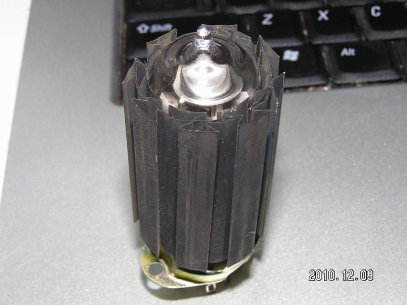
Yes, so I was asking where to get more of such heatsinks like on the picture in the 1'st post.
But tubes on edge of the chassis and zigzagged mirror behind them would look better.
Last edited:
1st post! Dude...that's more than 20pages from here. Like I have the time. So I appologize for jumping in without taking the botherings to read the thread, but just seeing the last page kinda gave me a clue I think.
Those heatsinks look pretty cool to me, a mean industrial Gothamish look. But isn't it bad to combine metal to glass b/c of the heat gradients you'll have at the contact points? I know I've read that. In the RCA manual I think.
Go Tubelab's way...don't worry about it, if it blows up, it's just plain fun!
Go Tubelab's way...don't worry about it, if it blows up, it's just plain fun!
In my years of abusing tubes I have only had two that exploded by shattering the glass. One was a cheap Chinese KT88 in a guitar amp, and the other was a 6С19П. Of course I was stupid enough to plug it into a 7233 socket without checking the pinout. 10 amps of heater current (much more into a short) went through the two plate pins that are connected internally causing rapid dissasembly of the tube!
After that fun moment I rewired the socket and tested the 6С19П for a cathode follower output stage.
...and it still worked? Wow, that's a military stuff!
- Home
- Amplifiers
- Tubes / Valves
- Heatsinks for tubes?