He has posted multiple pictures of his O2 on head-fi.if csa did not respond to those pictures request, i kinda start doubting that he even has ever built an o2. lol
i mean, it kinda weird, really. pictures can't do you no harm nor we will troll you for your terrible soldering skills
Specifically in the first post : O2 Build Complete: Let the objective, subjective listening tests commence!
and here : O2 Build Complete: Let the objective, subjective listening tests commence!
Despite his rather controversial claims, it is unfair to say he doesn't have built one.
He has posted multiple pictures of his O2 on head-fi.
Specifically in the first post : O2 Build Complete: Let the objective, subjective listening tests commence!
and here : O2 Build Complete: Let the objective, subjective listening tests commence!
Despite his rather controversial claims, it is unfair to say he doesn't have built one.
actually i was encouraging him to post another picture. because if you've seen his posts lately, you will understand what i'm talking about
.... What could I try?
I don't see anything out of place in the photos. For starters, if you have a meter, do the test I posted here for BobSaysHi and lets see if your power supply is OK. Note that this test is with the power switch "off" - out position. In your case you would measure to those pads where the battery terminals would be, since you don't have battery terminals soldered in yet. Alternatively you could measure to either side of those big R1 and R2 resistors.
http://www.diyaudio.com/forums/head...headphone-amp-diy-project-19.html#post2797483
You should read somewhere within +/-0.1Vdc of +/-12.0Vdc.
If that works then do the same voltage measurements between ground and the battery pads with the power switch "on".
Last edited:
actually i was encouraging him to post another picture. because if you've seen his posts lately, you will understand what i'm talking about
yes, we gather it isnt stock, thus the improvements......
Failed regulators and degraded performance don't really count as "improvements", do they?thus the improvements......
Failed regulators and degraded performance don't really count as "improvements", do they?
well he certainly claimed night and day audible improvements from his mods
I guess some still havent learned to recognise sarcasm =)
I don't see anything out of place in the photos. For starters, if you have a meter, do the test I posted here for BobSaysHi and lets see if your power supply is OK. Note that this test is with the power switch "off" - out position. In your case you would measure to those pads where the battery terminals would be, since you don't have battery terminals soldered in yet. Alternatively you could measure to either side of those big R1 and R2 resistors.
http://www.diyaudio.com/forums/head...headphone-amp-diy-project-19.html#post2797483
You should read somewhere within +/-0.1Vdc of +/-12.0Vdc.
If that works then do the same voltage measurements between ground and the battery pads with the power switch "on".
It looks just fine to me, was the exploding opamp turned in the wrong direction? What about the diodes, are they pointed right? They are a bit hard to see the direction on.
Brgds
It looks just fine to me, was the exploding opamp turned in the wrong direction? What about the diodes, are they pointed right? They are a bit hard to see the direction on.
Checked then and checked now again:
All diodes are in correct direction.
The amp directions were correct too, double checked before first power on.
I will do the suggested measurements later and report on that. Still curious about the reason why the LED stays off since the error occured.
I need a little solder advice. I've noticed that the solder in the BOM is a measly 18g for a relatively high price; high compared to Amazon, that is. Keeping in mind RocketScientist's warnings about radioshack solder and stained glass windows I am avoiding ebay possibilities but I would rather your advice if I were to get some from Amazon.
What do you think of these better value examples (on the cheaper end of what amazon offers)?
http://www.amazon.co.uk/0-8mm-Diame...CJ2W/ref=sr_1_1?ie=UTF8&qid=1322926251&sr=8-1
Solder with Cored Flux 100g 60/40 Tin Lead Resin 1mm: Amazon.co.uk: Electronics
http://www.amazon.co.uk/Solder-Wire...7D12/ref=sr_1_9?ie=UTF8&qid=1322936179&sr=8-9
http://www.amazon.co.uk/Weller-40-1...24/ref=sr_1_11?ie=UTF8&qid=1322936179&sr=8-11
Or perhaps something more expensive?
http://www.amazon.co.uk/Solder-60-H...8O/ref=sr_1_31?ie=UTF8&qid=1322936305&sr=8-31
Some can be really expensive:
http://www.amazon.co.uk/Leading-WK618-1-2mm-safety-MULD618i10/dp/9801658983/ref=sr_1_76?ie=UTF8&qid=1322936618&sr=8-76
It's .5K but do the maths and that's pretty pricey.
Is it substantially a matter of getting what you pay for or will I be just fine with those cheaper examples?
Am I going to end up in the depths of bitter regret? Should I get RS's BOM reel also at least for this project? How many baords do those 18g reels do, any way?
A related question: I've been attracted to the idea of getting a smoke extractor/filter but since I'm not going to be doing this all day every day do you think that I can get away with just a simple cheap desktop fan to blow away the smoke? I don't fancy opening the door to the outdoors as a another alternative.
Thanks for any help.
And thanks to RocketScientist whose clarity and objectivity and seemingly transparent expertise are truly a delight to behold. By gum it's nice to think one is really getting some facts.
Still curious about the reason why the LED stays off since the error occured.
Agreed! That is why the voltage measurements. If you get +/-12Vdc with the switch off, then your power supply is OK, at least with no load. And when you turn the switch on (all the chips still out, of course) if you get +/-12Vdc then things get interesting, since the power LED and a series resistor are right across the power supply rails after the power switch.
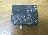
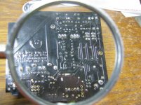
Also FWIW, here is a picture of the backside of one of my unmodified boards. Your solder joints are fine, but it is easy to "flood" them with solder if the solder is too big. I've actually been using 3 sizes of solder, which helps: 0.015" for surface mount and the very smallest O2 holes; 0.022" for most of the pads on the O2; and 0.050" for the bigger pads like the battery terminals and power jack. Looking at your board I'm guessing you may have used 0.050" or larger for most of the holes. The tiny tip I'm using on the iron helps a bit too, but solder size is probably a bigger factor.
Attachments
Last edited:
In consideration of building a low-power/long-battery-life model I've understood that it wouldn't be able toi supply high current phones but that high voltage phones would be fine.
Am I right in thinking that high current is the preserve of planars/ortho-dynamics, and that conventional drivers only go high voltage? Perhaps not but true generally, as a rule of thumb.
Are there high current conventional driver phones?
Am I right in thinking that high current is the preserve of planars/ortho-dynamics, and that conventional drivers only go high voltage? Perhaps not but true generally, as a rule of thumb.
Are there high current conventional driver phones?
Are those pics of a completed board, agdr?
Also FWIW, here is a picture of the backside of one of my unmodified boards. .....
Checked then and checked now again:
All diodes are in correct direction.
The amp directions were correct too, double checked before first power on.
I will do the suggested measurements later and report on that. Still curious about the reason why the LED stays off since the error occured.
The LED is literally right after the power switch. The voltage from the LED is used by the power management comparator (U2) but the LED itself should come on even with U2 not installed. Where it's drawn on the schematic might not make it obvious, but it's literally hardwired to the power switch.
So if the LED isn't coming on, on AC power, the only possibilities are the LED itself, R6, a bad solder connection/trace, a short or something drawing way too much current (the regulators would get hot), or something upstream of the power switch which is easy enough to check if you have a DMM. Pins 3 and 6 of the switch should be close to 24 volts with the power switch on. If not, are the regulators getting hot? If so, there's a short or bad component somewhere in one or both rails to ground or shorting the rails to each other.
If there's 22+ volts across pins 3 and 6 of the power switch, check the voltage across R6, it should be about 21-22 volts. If it's the same as you measured across the power switch, the LED is either shorted, or there's a solder bridge. If the voltage is much less than 21 volts across R6, the LED has either failed open, or isn't soldered fully, or the traces to it are damaged.
You can check the voltage directly at the LED terminals. It should be around 2 volts. If it's much higher, the LED is bad (or in backwards). If it's much lower but not zero the LED is bad. If it's very close to zero the LED is bad or there's a solder bridge.
Are you using battery or AC power for your testing? One other person installed the battery terminals backwards which will also keep the LED from coming on and can damage the op amps but probably not make them explode (the otherwise high reverse current is limited by the 220 ohm resistors R1 and R2). So, regardless, make sure the "+" terminals of the batteries are the left (input side) of the board.
Thanks for the kind words! I try... with mixed success sometimesI need a little solder advice.
<snip>
A related question: I've been attracted to the idea of getting a smoke extractor/filter but since I'm not going to be doing this all day every day do you think that I can get away with just a simple cheap desktop fan to blow away the smoke? I don't fancy opening the door to the outdoors as a another alternative.
Thanks for any help.
And thanks to RocketScientist whose clarity and objectivity and seemingly transparent expertise are truly a delight to behold. By gum it's nice to think one is really getting some facts.
")
You're not likely to suffer any ill effects from soldering a single O2 without a smoke extractor. If you have any sort of fan of any size or kind you can set it up somewhere to blow the smoke away from you. But people soldered all day every day for decades with the smoke in their face without too many associated ill effects. Widespread use of the extractors didn't really start until the 90's or so. So I wouldn't worry about it too much.
Any solder of approximately the right diameter with a rosin core and around 60/40 should work OK. The stuff from Mouser in the O2 parts list is fine, and cheap, if you are going to order parts from them. For all I know even Radio Shack solder might be OK these days, or something you can find at the local big box home improvement store. But there are some solders made for other purposes, and/or with really lousy rosin flux, that are not suitable or will be frustrating to use.
You don't need to spend more than a few dollars. The 1 pound spools have become really expensive--in part because there's some sort of tariff on lead now. But you just need one of the little tubes with at least a meter (yard) of solder in it. The silver solders, etc. are just a waste of money for this application.
I need a little solder advice. I've noticed that the solder in the BOM is a measly 18g for a relatively high price; high compared to Amazon, that is.
Stay away from 60/40, use 63/37. It doesn't sound like much of a difference but 63/37 is eutectic and much better to work with. Something like this. I see you are in the UK, I have no idea where to get good solder at a decent price there.
In consideration of building a low-power/long-battery-life model I've understood that it wouldn't be able toi supply high current phones but that high voltage phones would be fine.
Am I right in thinking that high current is the preserve of planars/ortho-dynamics, and that conventional drivers only go high voltage? Perhaps not but true generally, as a rule of thumb.
Are there high current conventional driver phones?
Yes there are. A good example would be AKG K701/702s which need a fair amount of both voltage and current. Other AKG models (especially some that are no longer offered) are even more hungry.
The problem with the low power TI op amps (actually the majority of common op amps) is they have high distortion into low impedances even at relatively modest currents. The TI parts specified for the long run time version of the O2 are rated for much lower impedances than most, but their distortion still rises fairly dramatically as the load impedance drops--even at only 0.5 volts of output.
So even a headphone like the 25 ohm Denon AH-D2000, which is fairly sensitive so it doesn't need a lot of voltage or current, will still result in higher distortion than the NJM4556. That just leaves the question of will the "more distortion" be audible? And that's harder to answer. Even with the TI op amps, the O2 still has lower distortion into a great many headphones than some other well liked headphone amps.
Do you have some particular headphones in mind?
@Shamharoth, if those are the really hungry ones that are no longer made, they're on the edge of the O2's abilities. So it would come down to how loud you like it and what kind of music you listen to. On AC power the O2 is good for 7 Vrms (20V p-p) See: More Power (if you haven't already)
- Home
- Amplifiers
- Headphone Systems
- The Objective2 (O2) Headphone Amp DIY Project