Soft start circuitry HAS to connect directly to the AC input (after the on-off switch) and then directly to the toroid transformer for it to work. Why would you need an isolation transformer? I usually use an AC light bulb after the on-off switch. Is that unsafe too? Please explain, I need the education.
the normal way AC is sensed should be on the secondary side of the transformer, before it reaches the bridge rectifier.
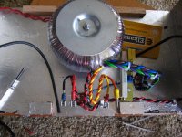
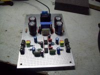
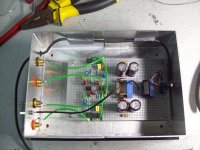
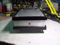
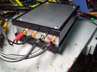
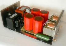
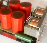
Pics below are of amp in progress (fully working), Mini aleph, Class A, +- 10W per channel, dissipation +- 40W per channel.
Attachments
Last edited:
similar to the above i made also a small Riaa .... in both cases the trafo is housed in an outside wall pack ( we do have empty housings for trafos capable of 2x18v 10W )
that come very handy in situations like that .
some photo....
that come very handy in situations like that .
some photo....
Attachments


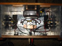
This is an MP3 player embedded in the frame have an old receiver.
Amplifier to a stereo amplifier is 25 watt،I used the IC TDA2009A.
25 volt power supply is،It can be used to feed my old printer.
It's the opposite of the view
Amplifier to a stereo amplifier is 25 watt،I used the IC TDA2009A.
25 volt power supply is،It can be used to feed my old printer.
An externally hosted image should be here but it was not working when we last tested it.
It's the opposite of the view
An externally hosted image should be here but it was not working when we last tested it.
This is an MP3 player embedded in the frame have an old receiver.
Amplifier to a stereo amplifier is 25 watt،I used the IC TDA2009A.
25 volt power supply is،It can be used to feed my old printer.
An externally hosted image should be here but it was not working when we last tested it.
It's the opposite of the view
An externally hosted image should be here but it was not working when we last tested it.
Very interesting, can you share more detail?
Shah,
what is the purpose of this?
what is the purpose of re-posting the same pics?
what is the purpose of this?
Apex,1,907px × 1,066px
what is the purpose of re-posting the same pics?
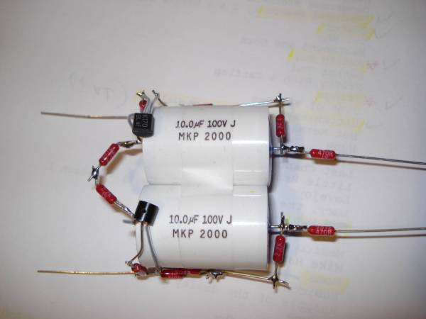
This is my version of the OBH 8SE Phono amp:
electrolytic capacitors in signal path replaced with film-type capacitors;
Power supply based on LM 317 but with batteries sounds little better for me.
Overall I am satisfied with the sound - i like it - it sounds more detailed then my Pacific style RIAA because the THD is lower, i think so.
inside:

Back panel (i still use old TT with DIN connector-do not want to damage the original TT)

front (with Leach amp)

electrolytic capacitors in signal path replaced with film-type capacitors;
Power supply based on LM 317 but with batteries sounds little better for me.
Overall I am satisfied with the sound - i like it - it sounds more detailed then my Pacific style RIAA because the THD is lower, i think so.
inside:
Back panel (i still use old TT with DIN connector-do not want to damage the original TT)
front (with Leach amp)
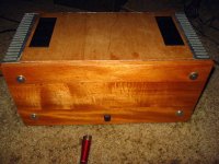
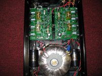
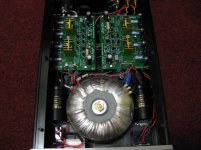
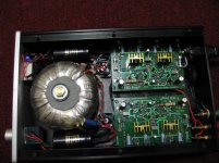
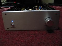
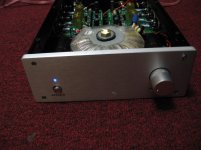
My new integrated amp!
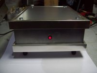
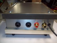
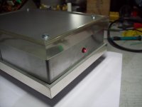
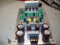
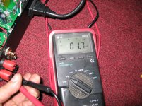
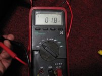
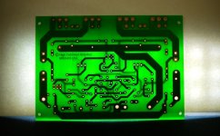
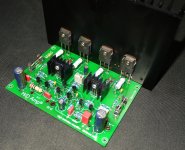
Here some pictures of my new integrated amp. The design is from HDamplifier.com. This is my second time that I order from them. The first time I build the T300 and now is the M400. the offset I get is 1.7 mv Left channel and 1.8 mv Right channel. The sound is very nice,I am using the chassis as a heat sink, it gets warm and if I push it..it get a little hot. I will put external heat sinks in the future. I am happy with the results!!! Excellent kits.")
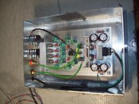
By the way, the whole chassis is aluminum and the side is really thick, but as I said before, I will put external heat sink in the near future.
Here some pictures of my new integrated amp. The design is from HDamplifier.com. This is my second time that I order from them. The first time I build the T300 and now is the M400. the offset I get is 1.7 mv Left channel and 1.8 mv Right channel. The sound is very nice,I am using the chassis as a heat sink, it gets warm and if I push it..it get a little hot. I will put external heat sinks in the future. I am happy with the results!!! Excellent kits.
By the way, the whole chassis is aluminum and the side is really thick, but as I said before, I will put external heat sink in the near future.
Attachments
-
 IMG_3677.jpg538.6 KB · Views: 520
 -
 IMG_3678.jpg430.7 KB · Views: 548
 -
 IMG_3679.jpg418.4 KB · Views: 377
 -
 IMG_3683.jpg353.9 KB · Views: 255
 -
 IMG_3681.jpg416.1 KB · Views: 350
 -
 IMG_3684.jpg601.5 KB · Views: 189
 -
 IMG_3687.jpg363.1 KB · Views: 153
 -
 loss%20noise%20pcb.jpg134.2 KB · Views: 273
 -
 M400%20amp.jpg363.2 KB · Views: 542
Last edited:
Here some pictures of my new integrated amp. The design is from HDamplifier.com. This is my second time that I order from them. The first time I build the T300 and now is the M400. the offset I get is 1.7 mv Left channel and 1.8 mv Right channel. The sound is very nice,I am using the chassis as a heat sink, it gets warm and if I push it..it get a little hot. I will put external heat sinks in the future. I am happy with the results!!! Excellent kits.
By the way, the whole chassis is aluminum and the side is really thick, but as I said before, I will put external heat sink in the near future.
replace the wiring of the pot .... to close to the trafo it will pick up something there i think .... go for shielded cables .....
- Home
- Amplifiers
- Solid State
- Post your Solid State pics here