No, the DC is a DC wave fluctuating between 11Vdc and 13Vdc.the dc is an ac wave fluctuating between 11v and 13v.
This fluctuating signal could cause deformations of the mechanical components as a result of the compliances that MUST be built into the relay mechanism to allow good switching action.
Could the hum be those relay vibrations?
Intermezzo
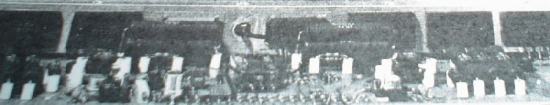
Sanken outputs driven by 70-90MHz Toshiba A1094/C2564, plus pre-drivers.
Biased real hard, see stacked power resistors of the drivers.
Burmester 828, 1982-August !
Samia Farah - Cool (Barbare) - YouTube
latest- greatest
Sanken outputs driven by 70-90MHz Toshiba A1094/C2564, plus pre-drivers.
Biased real hard, see stacked power resistors of the drivers.
Burmester 828, 1982-August !
Samia Farah - Cool (Barbare) - YouTube
Attachments
No, the DC is a DC wave fluctuating between 11Vdc and 13Vdc.
This fluctuating signal could cause deformations of the mechanical components as a result of the compliances that MUST be built into the relay mechanism to allow good switching action.
Could the hum be those relay vibrations?
Could be. Maybe the circuit needs to be
Modified a bit?
relay coil supply.... ac & dc
You should not use an ac relay with a dc supply working on AC the coil in an impedance with a resistance an a inductance in dc only the resistance will limit the current.
You should not use a dc relay with an ac supply the inductance of the coil will be too high and will limit the current too low unless you use a very high voltage supply and anyway it will not work properly.
Also an AC coil for a relay use a "shading coil" to revent "buzzing" this shading coil maintain some magnetic flux when the current of the coil cross zero.
Hysterisis of the relay will also change ( pick up voltage & drop out voltage ), in a ac relay the current of the coil is 400% the working current when the nominal voltage is applied and the magnetic circuit is still open, when the magnetic circuit close the reluctance drop, and more magnetic lines are present inductance rise and current drop.
Relay is dc 12v type. I have attached the ltspice schematic files so you can simulate what is happening using ltspice.
Regards
Simon
Attachments
are you sure the power transformer that you are trying to soft-start is actually good? is it a toroid? what's loading the transformer? any backwards electrolytics?
just trying to check all the bases ...
mlloyd1
Electrolytics installed ok. Transformer is Nuvotum from RS.
Have you powered up through a bulb tester?
When the bulb stays on, you know there is something that needs investigation and fixing.
Unfortunately I didn't do that. I have uninstalled the soft start. I was playing music at work through it for 12hrs ok. Took it home this morning and did some loud volume tests. After about an hour I heard music go soft and then stop so I run to the amp only to find 2 fuses popped on one channel and the resistors across the fuses in flames. Turned poweroff and blew out the flames. It seems I have 2 blown npn transistors and 1 pnp power transistor. I wonder if they might be fakes that can't handle it when decent power is drawn??
Regards
Simon
If I hear the transformer objecting then I get worried and investigate.
I will prove that it is wired correctly.
I will prove it is loaded correctly.
I will fuse the transformer to help prevent catastrophic damage.
I will not continue to use the complaining transformer+amplifier combination until it destroys itself !!!
I will prove that it is wired correctly.
I will prove it is loaded correctly.
I will fuse the transformer to help prevent catastrophic damage.
I will not continue to use the complaining transformer+amplifier combination until it destroys itself !!!
If I hear the transformer objecting then I get worried and investigate.
I will prove that it is wired correctly. Done
I will prove it is loaded correctly.Please explain how to do this
I will fuse the transformer to help prevent catastrophic damage.
First thing I ever do
I will not continue to use the complaining transformer+amplifier combination until it destroys itself !!! Transformer is not complaining as I have removed the soft start circuit!!! Amp was set with offsets for both channels at 0mv and bias at 20mV between 2 test points as per ostrippers instruction sheet.
Regards
Simon
I would test the transformer wiring via the bulb tester.
I would measure the voltages available.
I would connect the next stage of the load, the rectifier. Repeat the bulb start up and compare voltages.
I would add the smoothing caps and repeat, finally comparing voltages.
Then add one amplifier and repeat. etc. etc.
If the bulb goes on at any stage then something is wrong. If the output voltage from the PSU suddenly drops then something is wrong.
Have tested power supply without being connected to amplifier board and I get +ve and -ve 61v rails and bulb is not on. (ok)
When connected to amplifier boards +/-ve 50vdc and bulb is on very very slightly(hardly glowing)?
Theres some issue with my amplifier board somewhere.
What is the best place to start now? Maybe remove the power transistors and driver transistors and see if input bumps back up to 60v?
Edit Just found a shorted Q15 driver transistor.
Another question. Is it ok to use a 2sc3953 transistor as Q13??
Regards
Simon
Last edited:
I assume page 1 schematic is current, showing Q12.13 as drivers MJE15030/1. They are T0220s and able to drive huge current (8 amp max.) - much more than the little TO126 video drivers you ask about which are only suited to the VAS duty (200 mA). In a word, Nope!
Indeed, if those drivers blew, you have a serious problem there, whether the outputs were fakes or not. I hesitate to go further since you already had several hours smooth operation. From that point, you could have had oscillation or thermal runaway. This could have been triggered by the air temp. rising gradually, sense transistor not in good contact or simply the programme.
You need to get it going again with those big drivers though and scope it for oscillations or simply note excess heat for the bias current used. Expensive, aren't they?
- Home
- Amplifiers
- Solid State
- diyAB Amp - The "Honey Badger"