Jan's linear PSU was a revelation, and brought my unit into audiophile territory.
Quick question: are you actually using the +/- 15V supplies for analog audio input or output? Reason I ask is I am not; digital input and transformer coupled output directly off the D/A pins. If you have experienced improvement due to the 15V supplies, I will not realize it.
The only significant area I can assume improvement (specific only to my mod) is with the 5V analog supplies for the DAC's, which I have improved to a degree, but am still using the factory switching supply for the 8V rail.
Hi Linux,
Red LEDS on digital input, everybody agrees that's it's not a problem. But on the channels outputs that's different. Do the individuals levels are as close as possible of 0dB, or at least not in exaggerated gain ? Don't you use also too much gain in the EQ bands ? Then the solution is very easy.
even if I disable the eq (its disabled right now anyway) I still see reds on outputs, sometimes. mostly its when I listen to 'internet radio' which is known to be clipped and compressed to hell (and mp3 low bit rate, as well). my older cd's never get into the red region but most of the internet 'radio' stations do, almost every song has lots of red to it.
when I used the master atten on the dcx, I'd have to lower things by at least 2 or 3db before the red would finally stop happening.
so, we know the input meters are 'padded' but I suspect the outputs meters are also using the same 'round up' integer math, so to speak.
A fortnight ago, I fitted Frank Oettle's SRC/Clock mod, following Jan Didden's linear PSU in early summer, and his active I/O 2 years ago.
my dcx is still pure stock; but I plan to tap into the i2s outputs and run 3 external dacs from that. it looks like a wiring nightmare to do well but I have a hunch that all the timing and psu issues will be less of a negative effect if I use the box as JUST a digital i/o center and do all the d/a conversion outside using trusted dacs from another DIY project.
I might try hdmi as a way to get high speed i2s out of the box and into my set of dacs. or some other cable that has what it takes to transport a short bit of i2s and not blur it all to hell
")
not sure that cleaning up the audio inside the dcx is where I want to spend time and money, but I understand others wanting to.
if I eliminate all analog from the dcx, the meter redness is only a cosmetic issue after that
Pano, I knew(...) that you would read French. The subtractive architecture merits have been commented by real specialists (JohnK...), I will not risk any comment. Just that it's do-able with little skills.
I never did it because the per channel EQ has not to be used (only the general A & B can) and this, my actual BS drivers will not accept.
I never did it because the per channel EQ has not to be used (only the general A & B can) and this, my actual BS drivers will not accept.
If you see clipping lights on the outputs, that's a different matter.
It was a good question as it made us look deeper into what is going on.
Thanks Pano, and everyone else for the feedback!!
But as others have mentioned, even without EQ, or Gain (Boost), I do still see the output LEDS in the Red.. I'm only using crossover settings..
If I can see (with Goldwave) that the digital content is not clipped but just mastered 'too hot',, then I can asusme that even when the output LEDS are flashing Red, that it's safe and only "padding"..??
If this is the case, then all I need to do is study the schematics and work out a way to wire in a switch to turn-off the level indicators,, becaus it sure is 'nerve racking' seeing all those red lights flashing!!
When using analog input, it's not an issue, because using the Didden active i/o, I can set analog level for "Not too hot" before the A to D conversion.. But I honestly prefer digital input
Ta
CM
I don't see how you would get the output red light flashing if you aren't using any boost. Since the crossover divides up the signal, there is going to be less of it on each section.
Of course a peak at some frequency inside the filter band could drive it red, but it's rare to see that with music. Are you seeing red on the outputs?
I use a shelving filter so there is a good bit of boost. Rarely a problem with music, but swept sine test signals will certainly go red.
Of course a peak at some frequency inside the filter band could drive it red, but it's rare to see that with music. Are you seeing red on the outputs?
I use a shelving filter so there is a good bit of boost. Rarely a problem with music, but swept sine test signals will certainly go red.
I don't see how you would get the output red light flashing if you aren't using any boost. Since the crossover divides up the signal, there is going to be less of it on each section.
Of course a peak at some frequency inside the filter band could drive it red, but it's rare to see that with music. Are you seeing red on the outputs?
I use a shelving filter so there is a good bit of boost. Rarely a problem with music, but swept sine test signals will certainly go red.
Yes, I see Red on the outputs,, if the input is in the Red, then mostly the outputs will be too.. Only attenuating the 'input gain' control will reduce the level on the output LEDS..
Also, hard for me to explain,, but I find the opposite to what you say regarding crossover settings?? I find that when I use crossover, the levels on the outputs are higher! (perhaps more efficient since it's less bandwidth?).. If I use a passive crossover (bi-amped) and leave all crossovers turned off, then yes, the output levels match the input levels.. But, once I apply crossovers, the outputs do 'peak' higher than the input level ocassionally, particularly the mids..
CM
Well that's strange, it shouldn't. You don't have any of the output gains run up, do you?
Once you break the signal up into parts, each part HAS to be less than the whole, if you see what I mean.
No, I 'm not using any gains or EQ,, only crossover..
Yes, I see what you mean,, but do get my theory of Reduced bandwidth, hence increased efficiency?? Either way, perhaps someone else can chime in with their own experience..
With GoldWave, when I use "vertical zoom",, what are the values on the Y axis?? I thought it was dB values,, but the max is 1 and the min is .8.. So 1 equals 0dBfs,, am I correct??
Thanks!
CM
Quick question: are you actually using the +/- 15V supplies for analog audio input or output? Reason I ask is I am not; digital input and transformer coupled output directly off the D/A pins. If you have experienced improvement due to the 15V supplies, I will not realize it.
The only significant area I can assume improvement (specific only to my mod) is with the 5V analog supplies for the DAC's, which I have improved to a degree, but am still using the factory switching supply for the 8V rail.
Hi zigzagflux,
Thank you for your response.
I am not sure what you're asking, nor am I sufficiently competent on anything in particular to state a well-grounded opinion on specifics. I decided to share my experiences with the available mods because there have been some (somewhat shrill) opinions on this thread with which my ears begged to differ, or at least to challenge.
In my limited understanding of the situation, replacing the stock switched-mode PSU with a linear supply removes - at least - HF energy from the interior of the unit - energy which can no longer be picked up by induction elsewhere. Further, Jan's design provides for more solid regulation of all rails than stock. Why and how Jan chose the design and layout of his PSU is beyond me (but I'd of course be interested to know his various rationales).
Let's not forget that Behringer *could* have opted for better [loads of stuff], but chose instead to aim for lowest point-of-sale price. But it is to our benefit that this was their choice - after all, how many threads exist on modding a dbx Driverack, Rane whatnot, or Omnidrive?
If I have learned anything through building the various kits and mods that have been the backbone of my hobby these past few years it is this: 1) without a solid supply of power, forget fidelity; 2) with anything digital, you need that same solid supply of power, *and* a solid clock. Jan and Frank provide.
Sorry, that doesn't really answer your question, but there you go.
Happy Equinox!
Boink
PS, IIRC, the +15V is for the front panel display, not audio
Thanks for the answer. Those of use how use the digital input and then run straight out of the DAC chip to our own output stage don't use the +/- 15V supplies. Just the 3.3V (digital) and 5V (analog) supplies.
Replacing the super cheap electrolytic caps used on those supplies with better quality and a larger value seems a smart move. That's what I've done. Maybe not as good as a brand new PSU, but a step in the right direction. That 5V supply is the origin of your output signal. Nice to have it right.
Replacing the super cheap electrolytic caps used on those supplies with better quality and a larger value seems a smart move. That's what I've done. Maybe not as good as a brand new PSU, but a step in the right direction. That 5V supply is the origin of your output signal. Nice to have it right.
Exactly, I did the same; just upgraded the DSP board lyrics with organic polymer, and also swapped in a slightly better 7805 for the D/A power supply. I did get a measurable improvement as shown in another thread.
Also removed the 7805 feeding the A/D, as they are unused. Now I have extra capacity on the 8V supply since the 2nd 7805 is out.
So, autopoiesis, if you are still using the stock I/O board you are in fact using the +/-15V supplies for the opamps, therefore I would not be surprised to hear you have improved the sound with PS upgrades. I was most curious to know the benefit, if any, of improving the 3.3V and 5V supplies.
The 15V it is true is used also for the front panel display; curses !! If that were not the case, I would have enough room to provide my own linear supply without ANY 15V supplies- just 5V, 3.3V, and a dedicated 5V for the D/A.
In Goldwave you can set the X & Y axis values. I use the dB scale on the Y axis.
Got to: Window/Options
Thanks Pano!
I'm really enjoying GoldWave,, especially the 'analog vu' meter
Now I better understand the correlation between the DCX level LEDS, and the actual analog voltage levels within the spdif stream..
Cheers!
CM
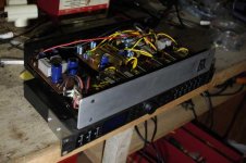
I can give you a live opinion : after the big amelioration with a linear PSU for the DAC (5V + 3.3V), I've been feeding each stage with an independent linear PSU (including the LED frontal display). All 317/337 based, in a separated rack screwed under the DCX for harboring the 9 circuits.
Honestly, it's not worth the job, I have not been detecting any striking improvement, and I don't even speak of the anxiety when you discover that there is a digital ground and an analogic one.
here a picture of an early stage, still is missing the +/- 15 V for the screen, the fans (all this get hot) and their PSU.
Attachments
Now that I have managed to understand the issue of the Red LEDS when using digital input, I am finding the level meters to be quite distracting and annoying!
I would like to wire up a small switch on the side of the case just behind the 'rack mount ears', that would allow the display to be turned on and off..
I have been studying the schematics, but I find the "control interface" page hard to interpret.. Can anyone help? Or has anyone already performed this mod??
Thanks..
CM
Wow Gazon, that's a piece of work! I had suspected that the 5V supply is not all that bad. Sure, we can do better, but would you really hear it?
CM, I'll have a look but I've never taken off the display panel. It may all be on a PCB that would be hard to mod. I'll look. If not, black tape.
CM, I'll have a look but I've never taken off the display panel. It may all be on a PCB that would be hard to mod. I'll look. If not, black tape.
If not, black tape.
Lol... Thanks Pano,, I suppose that would work,, but I also like to sometimes use the analog input, which I then use the Didden active i/o input volume control to set the analog just below clipping..
btw.. I am noticing with Goldwave, that sometimes the "max volume" doesn't correlate with the wave form when zoomed right in.. Do you notice that??
Eg, 'message in a bottle' shows max of 1.0 (+0.00dB) at 1:54, but zooming the Y axis at this time point, the wave form does not reach 0dB, and also the time seems a little out as well..??
Ta
CM
- Home
- Source & Line
- Digital Line Level
- Behringer DCX2496 digital X-over