With apologies to the mods, I originally posted this in the Instruments and amps forum, since it's for guitar ultimately, but there just isn't much traffic there, and I got very little joy. All the tube amp expertise is here.
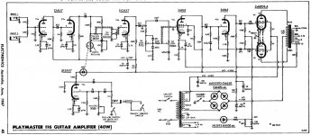
I'm trying to learn how to design an amp, so this is a project intended mainly to drag me through the process and calculations as a learning experience. The only design goals; small practice/recording amp, SE using a 6DQ6B since I have a couple dozen NOS ones in my junk box. I'm basing its topology on Bob Richard's Bluesman amp, but using different tubes, again, just to force me through the calculation process.
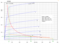
Here's a loadline I've created for the output. I graphically scaled the curves up to G2=175V instead of 150V, so they aren't exact, but should be really close.
Your advice is appreciated. (this is the 2nd stab at it. Thanks Michael K. for the first response.)
..Todd
I'm trying to learn how to design an amp, so this is a project intended mainly to drag me through the process and calculations as a learning experience. The only design goals; small practice/recording amp, SE using a 6DQ6B since I have a couple dozen NOS ones in my junk box. I'm basing its topology on Bob Richard's Bluesman amp, but using different tubes, again, just to force me through the calculation process.
Here's a loadline I've created for the output. I graphically scaled the curves up to G2=175V instead of 150V, so they aren't exact, but should be really close.
Your advice is appreciated. (this is the 2nd stab at it. Thanks Michael K. for the first response.)
..Todd
Attachments
Last edited:
Your advice is appreciated. (this is the 2nd stab at it. Thanks Michael K. for the first response.)
The 6DQ6 is not at all suitable for SE use. The most linear part of the characteristic lies well within red plate territory. If you take another look at that loadline, it strays out of the saturation region at a very low Vgk, just barely above Vgk= -30V. That's an open invitation to screen grid poofage, as the screen current will increase tremendously once you leave the saturation region.
If you're gonna use those 6DQ6s, best design a PP final. If you want to stay with SE, then E-Bay 'em for types more suited to SE, Class A operation.
See this thread for design walk-through I did.
Hi Miles,
In fact your walk-through is one of a handful I have printed out and re-read regularly, hoping one day for it to suddenly sink in and make sense. It's starting to now that I'm applying it. Thanks for writing it.
I'll take your word for it about the 6DQ6B being unsuitable for SE use. I just have a bunch kicking around, and the output power is about right in SE mode for a little practice amp, and I didn't want to buy anything for this. I'll see what else I have kicking around.
[rummaging...] Ooo.., I have a couple used 7189s and a pair of little companion SE output transformers from a donor console stereo. I'm sure they'll be fine for this. And I'll have spare set if I destroy the first attempt (or love it so much that I want a second one.)
Miles, I'd love it if you could elaborate on why the 6DQ6 isn't suitable; I don't know the term "saturation region" but it sounds like you are suggesting the operating point and load line are too close to bottom (0 mA) cut-off area. Also, I don't understand why the screen current acts as you say.
And for guitar amp purposes, how much should I be concerned about using a tube's most linear region? For hi-fi that's a no-brainer, but for guitar I may be wanting to purposely avoid it. I'm not really sure how the guitar amp guys approach that. But I do know that achieving that perfect distortion spectrum is an art-form I'd like to learn.
..Todd
Last edited:
Miles, I'd love it if you could elaborate on why the 6DQ6 isn't suitable; I don't know the term "saturation region" but it sounds like you are suggesting the operating point and load line are too close to bottom (0 mA) cut-off area. Also, I don't understand why the screen current acts as you say.
Look again at the plate characteristic you attached at the top of the thread. Everything to the right of the blue line is the saturation region. This is where the plate current becomes (more or less) independent of Vpk. It is also where screen current remains manageable. Straying outside of that drives Vpk to such low values that the plate becomes ineffective as an electron attractor, sending the screen current skyrocketing to possibly destructive currents. It's especially bad for any guitar amp design, given how axmen tend to abuse amps.
For any SE amp, the plate bias current should be about half the max signal plate current. The 6DQ6 and other TV horizontal deflection finals were designed to pull some big currents at Vpk= 0. For the 6DQ6, that's about 350mA. so you'd need a plate bias of 350/2= 175mA. At Vpp= 300V, that means that Pd= (300)(0.175)= 52.5W. The type is rated for Pd(max)= 18W. Granted, the TV horizontal deflection types are rated very conservatively, given the demanding nature of the intended service, and can stand some spec-busting for much less demanding audio amplification, but not that much. It'll red plate badly.
And for guitar amp purposes, how much should I be concerned about using a tube's most linear region? For hi-fi that's a no-brainer, but for guitar I may be wanting to purposely avoid it. I'm not really sure how the guitar amp guys approach that. But I do know that achieving that perfect distortion spectrum is an art-form I'd like to learn.
You wouldn't necessarily be so concerned about linear operation for guitar amp useage. However, you still need to consider staying within the type's saturation region so's you don't poof the screens. The only other alternative might be to use it as a pseudotriode, and keep the Vpp under the 220Vdc max specification for the screen voltage, unless you can determine if you can bust that spec without making the screens glow. Some of the TV HD types are more tolerant of this than others.
Okay, thanks Miles. I understand most of that. Regarding straying outside the saturation zone, you mean if the output voltage swings too much to the left (negative from bias point). But wouldn't that be the case in every tube load line? I'm not getting why this is more of a concern with this tube or load line. I guess there's something I'm still not seeing.
I'm going to tackle this with a 7189 instead.
..Todd
I'm going to tackle this with a 7189 instead.
..Todd
Okay, thanks Miles. I understand most of that. Regarding straying outside the saturation zone, you mean if the output voltage swings too much to the left (negative from bias point). But wouldn't that be the case in every tube load line?
Not if the loadline intersects the Vgk= 0 line. If that's the case, then you'll have grid clipping at the same point where the loadline leaves the saturation region, and the nasty sounding distortion will let you know you've turned the volume up too high. (It's something you need to watch out for with RF amps, as mismatched loads can cause the same problem, and high powered RF pents often incorporate screen grid over current protection.)
I'm not getting why this is more of a concern with this tube or load line. I guess there's something I'm still not seeing.
The original loadline leaves the saturation region at way below Vgk= 0, and so you won't have clipping distortion to let you know you're getting into possibly destructive territory.
Hi rsumperl,
Well, not really. I did see that (and others), but I won't learn much copying
a different design, or even just the operating points, so I purposely avoided
looking too closely.
..Todd
Hi,
Analysing existing designs, good and bad, are an
excellent way of checking your analysis skills.
If you can't do that, you can't design anything.
rgds, sreten.
The 6DQ6 is not at all suitable for SE use.
Confirmation....I didn't listen and wired them into a SSE and cranked them up. They don't like SE. I couldn't find any bias / load point where I could get more than a watt or two that was remotely useful for HiFi.
Back when I was about 12 I used to get tubes from old TV's and make guitar amps. I didn't know what a load line or impedance was but I knew how to make tubes glow red. I didn't understand why the little ones (6BQ6's) were louder than the big ones (6DQ6's). Some of those amps did crank though. You might be able to make an SE guitar amp from a 6DQ6 but I would look for something better. Save the 6DQ6's for a 75 watt P-P amp. Trust me they will rock for that application.
The 7189 may have some collector value. If you have 7189A's they ARE useful for amps that eat mere mortal EL84's. That said the 7189 is an excellent choice for a guitar amp both SE or P-P. Look at the AX 84 site for some design ideas.
Hi,
Analysing existing designs, good and bad, are an
excellent way of checking your analysis skills.
If you can't do that, you can't design anything.
rgds, sreten.
You are correct. I agree. I do that regularly, as well as I can make sense of them. What I meant is I don't want to just use someone else's calculation results and just copy and existing design. I'm trying to learn how to arrive at those myself. Existing ones seem to all make sense -- until I try it myself, then it becomes obvious what parts I don't really understand. That's what this little exercise/project is all about.
Also, the example offered was a PP design, mine is SE, so as far as operating points and loadlines are concerned, the details are not very applicable.
..Todd
Last edited:
The 7189 may have some collector value.
Mine are used (well used, by the looks of it), so I doubt there's much value (or even much life left) in these. They aren't 7189A's.
I'm pretty familiar with the AX-84 stuff. The 'high-octane' will be on my bench one day, but that's a different day. This day is for Bob Richard's Bluesman circuit. I'm trying to avoid looking at the AX-84 data until after I figure it out myself. Then I'll compare and see how bad my numbers are. This is an advantage over using 6DQ6's since there are no SE output sections available to check against. Tons of them for EL84 types.If you have 7189A's they ARE useful for amps that eat mere mortal EL84's. That said the 7189 is an excellent choice for a guitar amp both SE or P-P. Look at the AX 84 site for some design ideas.
..Todd
Last edited:
I'm not entirely agreeing with the assessment that the 6DQ6B cannot be used in SE mode (it's the same tube as a 6JN6 by the way, but to be honest I haven't built any SE amp using a pentode in pentode mode). To keep the screen grid current under control just means that the Vg2 needs to be reduced until the Vg1=0 curve's knee does intersect the load line. For the excessively high 10K load line chosen, this would require around 60V on g2. This would be rather wasteful of the current capability of the 6DQ6, but the power output would be the same, still limited by plate dissipation. The gm of grid 1 at such low currents will be rather low though, making the driver stage a headache, but then most SE tube types are rather low gm anyway.
The linearity looks bad at the low currents on the graph, but is somewhat of an illusion since it is still 3/2 power law everywhere. If one expands the scale then the low current curves look the same as the high current ones did before (easy to see on a curve tracer). What is lacking is that any pentode is distorting in SE mode with a 3/2 power law characteristic. What is needed is some type of Schade feedback to either the driver tube plate or driver cathode to give the whole thing some kind of Mu.
A lower load Z would make better sense since the Vg2 could be raised for higher idle current which would give better gm for grid 1. Then the OT and driver stage would be easier to make too. The linearity is the same as before despite looking bad on the graph with a steeper load line. Thats because the earlier high Z load line was just in a compressed region due to graph scaling. Magnify it up and they both look the same. Its the Schading that saves the day for either case.
A common miss-perception when looking at a 3/2 power curve directly (plate current versus Vg1) is that the more curved lower portion at the low currents is more distorting. This is not true. If you take the small curved section and rescale the graph you can overlay it on the original curve. Both are 3/2 power curves after all. Its the use of a small section of the curve relative to the full curvature that determines linearity in this mode (pentode). Using the more curved lower portion would just mean using a smaller section (reduced current range with high Zload and high B+) to get the same linearity (and power). Real tubes do however deviate from a true 3/2 power law, due to grid island effects and low gm effects at the grid ends, so there will actually be some difference in practice between high Zload and low Zload operation. Usually the tube datasheet's suggested operating range for a given class of operation gives the best results. High Zload operation gives better efficiency due to the reduced effect of the minimum plate voltage and the lower Vg2 there helps too, but the OT is harder to make and the higher B+ more dangerous.
Last edited:
Sometimes you can spend a lot of time with curves load lines and simulators. These things are all good tools to figure things out, but they don't make any sound.
I often use a different approach. I set the tube to be tested up in a circuit with everything adjustable. I have a driver that can blow the grid right out of the tube if needed (mosfet) so positive grid operation is not a problem. I have the screen tied to a 0 to 400 volt 200 mA supply, and the plate its own supply (4 to choose from) and several OPT's from 1250 to 12K ohms. I can use cathode bias if needed too. Many OPT's have UL taps so there are 3 possible modes of operation.
I have dialed in several unusual tubes this way, but the 6DQ6 just didn't want to cooperate. Granted I was looking at a HiFi design and all testing was done without feedback since a HiFi design should work good before feedback is applied.
Can the 6DQ6 be used in a SE guitar amp? Of course. Is it the best choice given its price (free). I don't think so. It would take some fussing around to make right, and the 7189 will just work. Now if you need more than 4 or 5 watts, there might be a better choice.....like push pull.
Now if you need more than 4 or 5 watts, there might be a better choice.....like push pull.
But if one wanted to stick with SE for that type of guitar sound, and get a bit more grunt, a GU50 might provide about 10W as a rough guess. Or even run a couple in parallel. Might be romantic amplifier... every time you turned it on, the lights would dim.
..Todd
Just want to correct an error I made in my above posting (#14) on the 6DQ6B dist. etc. The grid 1 gm does go down with lower operating current (higher Zload), but it scales down at about the SQRT of op. current, so the grid drive needed (for equal power output) actually reduces (op current swing reduced more than gm did), making the driver stage easier (not harder, as I erroneously said above) to construct. The reduced g1 voltage swing would reduce grid island distortion (a second order effect), so probably this accounts for the some of the usual observation of lower dist. at higher Zload. (another improvement would come from unloading the high Mu, high rp "triode" that the pentode really is ) At least up to a point. Going too far (too high Zload) will get one into grid 1 current distortion, when the g1 bias V gets low enough to be near the peak input signal.
Last edited:
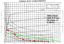
I don't see the problem with 6DQ6 as a SE guitar amp. I'm not following this "saturation region" problem Here's a 5K loadline. The datasheet gives curves for screen current which I've plotted roughly through the load line. Look at the screen current and check the average power. Look, no poofage. PEAK current is 15mA at 150V. G2 can dissipate 3.6watts. In a guitar amp circuit like a Champ the g2 is powered through a resistor, which will surely limit the g2 current to safe values.
Sure it's going to have it's own sound, but no one here can predict how it will sound from the information given. I'd sure give it a try. Heck, maybe I will...
Sure it's going to have it's own sound, but no one here can predict how it will sound from the information given. I'd sure give it a try. Heck, maybe I will...
Attachments
Last edited:
But if one wanted to stick with SE for that type of guitar sound, and get a bit more grunt,
I don't know how much the GU50 and its socket costs, but 15 watts or more can be extracted from a KT88 rather easilly without violating its specs.
If that isn't enough grunt and you are slightly deranged you could try this:
The 833A SE Amp Prototype
...
For any SE amp, the plate bias current should be about half the max signal plate current. The 6DQ6 and other TV horizontal deflection finals were designed to pull some big currents at Vpk= 0. For the 6DQ6, that's about 350mA. so you'd need a plate bias of 350/2= 175mA. At Vpp= 300V, that means that Pd= (300)(0.175)= 52.5W. The type is rated for Pd(max)= 18W. Granted, the TV horizontal deflection types are rated very conservatively, given the demanding nature of the intended service, and can stand some spec-busting for much less demanding audio amplification, but not that much. It'll red plate badly.
I think you're confusing PEAK signal current on a particular load line with the maximum rated cathode current. There is no reason at all to require the class A idle point of 1/2 the max rated cathode current. Where do you get this from?
- Status
- This old topic is closed. If you want to reopen this topic, contact a moderator using the "Report Post" button.
- Home
- Amplifiers
- Tubes / Valves
- Amp design exercise, mentorship needed...