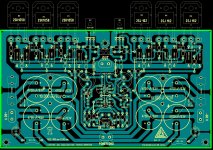
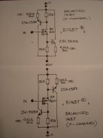
SSA IGBT version
To put another version to DIY maybe sombody will find this IGBT as the most suitable for him, lets see.
Another comment to my yesterday test with real PWS is about PSRR. I am impressed how good the +/-15V DC rails are in real SSA amp. They completelly serve the purpose without any need to have regulated or other kind of +/-15V supply whatsoever.
The result is impressive, at the speaker's tweeter there is absolutely nothing, no sound, black silence. So we really need PCB LEDs to show power on operation.
Attachments
DC offset stability
On more good thing about the SSA in any version, is DC offset stability. Once it set to 0V at the ouput, it is stable within +/-10mV regardless to thermal conditions of the output's heatsink. The only condition is proper thermal connection between input pair BJT's, so no need for any kind of DC servo circuits whatsoever.
On more good thing about the SSA in any version, is DC offset stability. Once it set to 0V at the ouput, it is stable within +/-10mV regardless to thermal conditions of the output's heatsink. The only condition is proper thermal connection between input pair BJT's, so no need for any kind of DC servo circuits whatsoever.
Hi buzzforb
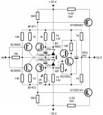
It all depends to rail's voltage potential, if it is 35V like on this last sch, than you would have only 0,1W power on thermal dissipation + 0,07W max extra dissipation at full signal present. So for +/-35V BC550C/BC560C are OK.
For higher rail voltages and thus power dissipation you would need TO-126 case for cascodes BJT's, like BF471/BF472 etc.
The most important thing to maintain quality of this symmetrical SSA design is gain factor equality for all complementary semiconductors in the circuit. The input pair is the most critical and it is recomended to choose current gain more than 600 +/-0,5% tolerance between NPN/PNP device, and similar to the other semiconductors.
In simple designs like SSA is, it is allways very important to choose the best parts possible.
Hi all,
Thanks for the interesting work.
I have a set of the world's most demanding speakers (Apogee Sinctilla). Impedance drops to 0.4 ohms on the mid range ribbon.
Would it be possible to use this amp with several paralleled output devices to drive such a difficult speaker?
What about using ut to drive 50ohm headphones?
The lateral fets are quite easy to drive....so it should be possible to extend to 6 set of output devices...Its possible to adjust the drive current by increasing the resistors to maybe 150 ohms and at the same time decreasing the spreader...6 pairs should have app 30 mA give or take a little... and plenty of current capabilities. think a version like that with app 45 V rails will do the job..
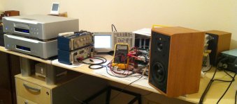
Later this evening I connected a sch from the post #217 to a real 200W power supply, +/-35V, 60mF caps bank to perform some more tests, at least that was the plan. At the end I only managed to make some small changes to Vbe multiplier but for an almost two hours I have listened to a music instead of doing some more measurements/experiments. Situation that happened so rarely in my DIY career - the sound was so good that I forgot to do anything else. The only explanation I can think of, to understand the sound quality presented, lie in the amp's phase-time-frequency characteristics. Sound was so naturally live when I went outside the lab, one could easily think it is the real stuff going in.
I am jealous ,whish i was there ,ho
Still listening & enjoying
Hehehe ... right now I am listening to the SSA "spider network", can't stop cause it sounds better than any of my amps in the house, so my lab is now the place to enjoy the music.
P.S. In these days I found out one really important, very crucial info to me, that SSA's diff-amp CF stage is my favourite front-end ever ... will never go back to LTP !!!
I am jealous ,whish i was there ,ho
Hehehe ... right now I am listening to the SSA "spider network", can't stop cause it sounds better than any of my amps in the house, so my lab is now the place to enjoy the music.
P.S. In these days I found out one really important, very crucial info to me, that SSA's diff-amp CF stage is my favourite front-end ever ... will never go back to LTP !!!
Attachments
Last edited:
the mje 350/340 could be an alternative...
ON MJE15030/15031 (for 3 output pairs, 60V rails), Philips original BD139/BD140 (if with 2 lateral pairs & 45V rails) I would think a bit more appropriate for drivers than 340/350 if Sanyo video transistors aren't available?
Hi Lazy Cat,
Is it possible to adopt the basic circuit of your SSA to drive a BTL bridged output biased as classA? How? The idea is to enjoy the sound of classA amp at higher power using say +/-35v rails, with so few parts its very interesting and wont be so difficult for newbies like me to build. Not sure though about the effect in efficiency.
Is it possible to adopt the basic circuit of your SSA to drive a BTL bridged output biased as classA? How? The idea is to enjoy the sound of classA amp at higher power using say +/-35v rails, with so few parts its very interesting and wont be so difficult for newbies like me to build. Not sure though about the effect in efficiency.
Lazy Cat,
I doodled a single ended version of your amp, with PP output stage using lat fets.
I kept moving along, reducing and refining - and I virtually ended up with a bipolar version of the FetZilla!!
We know the FZ sounds very good; by deduction we can assume that your design sounds equally good, I'm sure. What does stand out is the very small phase shift at 100KHz, impressive indeed.
Cheers,
Hugh
Hehehe ... right now I am listening to the SSA "spider network", can't stop cause it sounds better than any of my amps in the house, so my lab is now the place to enjoy the music.
P.S. In these days I found out one really important, very crucial info to me, that SSA's diff-amp CF stage is my favourite front-end ever ... will never go back to LTP !!!
Hi Lazy Cat,
Are you using the same B-IGBT configuration on your current SSA amp setup or are you currently using bipolar transistor?
Attachments
Hi Lazy Cat,
Are you using the same B-IGBT configuration on your current SSA amp setup or are you currently using bipolar transistor?
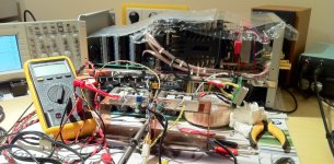
I am listening (also right now
) to exact sch from the post #217. As you can see there are two BIGBT's on the output (shining copper cases, each having three connection pins), runing on +/-35V. There is 0mV at the output at cold turning on (this morning), no turn on bump whatsoever, and still 0mV when hot. With these improvisational copper U-shape heatsinks (on the pic) it goes up to 70°C and more, but it is good to have overheating test as this is beeing performed to find out the best Vbe multiplier version to hold bias nearly constant.
Last edited:
Lazy Cat,
I doodled a single ended version of your amp, with PP output stage using lat fets.
I kept moving along, reducing and refining - and I virtually ended up with a bipolar version of the FetZilla!!
We know the FZ sounds very good; by deduction we can assume that your design sounds equally good, I'm sure. What does stand out is the very small phase shift at 100KHz, impressive indeed.
Cheers,
Hugh
Yes, these two amps have similarities no doubt about that, they're both CF and straightforward designs, not "complicate" with signal very much. I read all the thread of FetZilla and derivates and admit that I was tempted to built and listen one, but DC offset, turn on transition swing, freq compensation needed, somehow delayed my decision, than came SSA with its promising measurements, listening tests, ...
Agree, phase shift at 100kHz I will measure, but suppose it is very small, few degres maybe, will post it later. It is still surprising to me that SSA runs with no kind of feedback caps and I have never detected any hint of an oscillation on the scope.
Hi Lazy Cat,
Is it possible to adopt the basic circuit of your SSA to drive a BTL bridged output biased as classA? How? The idea is to enjoy the sound of classA amp at higher power using say +/-35v rails, with so few parts its very interesting and wont be so difficult for newbies like me to build. Not sure though about the effect in efficiency.
Two A-class amps in bridge configuration at higher output current levels than bias current value, does not keep any of them in A-class any more. So A-class is assured only at certain output currents depending on bias level set and you won't get any more A-class power in bridged amp because of double voltage swing, output current is the limit. Power dissipation level still acceptable (size of the heatsink, energy consumption acceptance, ...) is the only limiting factor. You can make single channel +/-50V A-class SSA if you like, don't need bridged amp for that only more output transistors. Beside that, your amp will be nice room heater in the winter times.

I added the 3.3 pF FB capacitors only to band limit the amp in case of spurious pick-up from the speaker cables. Some FM tuners 10.7MHz can radiate IF and the amp can still operate at that frequency.
Comparing subjectively between MOSFET and switching to BJT version I cannot detect any difference in sound character.
I used On Semi MJ15001 and MJ15002 for BJT and Rensas 2SK1058 and 2SJ162 for MOSFET. I do not have IGBTs so I wont bother. I personally choose the MOSFETs because the circuit is simpler.
Regards
Nico
- Status
- This old topic is closed. If you want to reopen this topic, contact a moderator using the "Report Post" button.
- Home
- Amplifiers
- Solid State
- Simple Symetrical Amplifier