Member
Joined 2009
Paid Member
I mostly design parallel symmetric and the solution is to bias heavy until 2nd harmonic dominates. There is also a point where 2nd and 3rd have the same amount and that is often the point where total distortion is minimum. I like some more 2nd then 3rd though.
Why does heavy bias in a symmetric amp lead to more 2nd ? and how much bias do you typically find necessary to get this type of profile ? and how do you perceive the differences in sound between lower and higher bias ?
(sorry for lots of questions!)
Hi Bigun,
I mostly listen to my office amp on my PC, it is a single ended front end followed by bootstrapped VAS and Lateral MOSFETs, very little odd harmonics, wide band and low phase shift.
Here is the harmonic distribution of my usual PC amp.
I mostly listen to my office amp on my PC, it is a single ended front end followed by bootstrapped VAS and Lateral MOSFETs, very little odd harmonics, wide band and low phase shift.
Here is the harmonic distribution of my usual PC amp.
Attachments
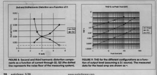
Bigun, i am not an expert in power amps. My forte is low level design. See a calculation made my Rossiter on his MC Headamp. At 4mA the distortion curves cross. See also the distortion over level of the Hiraga ( sigle ended no NFB ), the Leach ( parallel symmetric
no NFB ) and the Rossiter ( parallel symmetric current feedback ). The shape of that curve is the same although on different levels. This is THD so says nothing about the distribution of the harmonics. I whould bias the stage of Fig.8 to something between 5 and 6mA.
About the sound ? I talk only about subjective sound on my own thread .
Attachments
Maybe we place too much weight on harmonically related distortion. It could well be the bandwidth or relative phase change that has a greater subjective effect.
I am talking stupid stuff, again - after all we are designing a great little amp and that is more important, building it and listening to it is very satisfying.
I am talking stupid stuff, again - after all we are designing a great little amp and that is more important, building it and listening to it is very satisfying.
Last edited:
How about this output stage? Triple collector output (A970, B649, A1216)
Is it better or worse than Lateral Mosfet output stage?
if it is any good, what is the optimum bias for this output configuration?
Hi Lumanauw,
A similar output stage :

Simulation results can be found #29 here
http://perso.orange.fr/francis.audio2/Concours_Conception_Ampli.pdf
PS
Did you receive the Audioanalyse amp circuit I sent you ?
Member
Joined 2009
Paid Member
Thanks guys, this helps.
Nico, I may be finding a correlation that doesn't exist because of wishful thinking but I'd guess that your SE i/p amp sounds warmer than the SSA amp because of the difference in H2 content arising from it being asymmetric and not having high levels of gnf to reduce it. What interests me is the impression that the SSA is more 'vibrant' - it sounds like a desirable quality - can you say more about it ?
Joachim, that's an interesting plot. But I can't figure the physical reason for rising H2 with bias. Nelson says he has seen H2 in his symmetrical amps at low levels because of natural device mis-match but above 1V it's predominantly H3. Mind you at the low levels of distortion being simulated for SSA it may not matter !
Good question. That would require a spectrum analysis over level and frequency with a huge dynamic range. You can imagine that you end up with a universe of data.
Then putting that in perspective to what we hear and the Nobel Price is yours. I gave up on harmonic distortion measurement some time ago. I simulate it and then i listen.
Only a pathological bad SS amp does create more then 0.1% ( you can also put in 1% if you like ) of high order harmonics. There are even people that like that better then an amp that is clean but then it is mostly a SE tube on high efficiency speakers....
Hi Alex mm !!....... rev.1.4 final adjust")
Alex .
Since PCB draw very well at a given schematic, so please help to draw the PCB for this audio amplifier, and according to this schematic (circuit)!
thanks and cheers !!


Attachments
What a nice project and A VERY
Nice circuit....!!
Have juggled a little with it..(Nico's extended) Seems to have a superb way of distortion.. the 2. and 3. has total domination... .. also when the circuit is pushed hard
I have scaled it to 60 Volt rails...and changed the driver to TO126 parts.. increased the drive current to the laterals (3 set) to 20 mA. The higher rail's improves performance quite a bit...
I have kept the TO92 devices for the front end.. but I am a little suspicious of the heat dissipation as the cascode like set as it needs to dissipate 260 mW. Any takes on if this too much for the TO92 devices..??
Cheers Michael
Nice circuit....!!
Have juggled a little with it..(Nico's extended) Seems to have a superb way of distortion.. the 2. and 3. has total domination...
.. also when the circuit is pushed hardI have scaled it to 60 Volt rails...and changed the driver to TO126 parts.. increased the drive current to the laterals (3 set) to 20 mA. The higher rail's improves performance quite a bit...
I have kept the TO92 devices for the front end.. but I am a little suspicious of the heat dissipation as the cascode like set as it needs to dissipate 260 mW. Any takes on if this too much for the TO92 devices..??
Cheers Michael
Last edited:
Radio, why don't you send a request to Alexxmm via mail, else we are going to contaminate Lazy Cat's thread with all kinds of confusing things.Hi Alex mm !!
Since PCB draw very well at a given schematic, so please help to draw the PCB for this audio amplifier, and according to this schematic (circuit)!
thanks and cheers !!
Regards
Nico
Lazy/Nico
Here is my take on a straight forward higher power version...
I have changed the feedback values and path a little.. gain is 26 dB
I have also changed transistors and drive current for the mossfets. now ita app 20 mA and with 200 mA's through each output leg.
the two small caps C-8;C9 is just for simulation (PCB trace capacitance)
looks nice an simple...for practical implementation there are issues around back emf and RF..some are more clever than me on this, but could be that a coil and RF-snubber networks are needed..
I have been studying Alex's PCB and i think it can be improved on the earthing...the primary ground is at the input, think it ought to be next to the output.. then the input can lifted slightly to avoid dirty GND...
Could well be I'am mistaken though, just a thought..
Attachments
Last edited:
MiiB,
Nothing too shabby with your higher power version Michael. I think several followers of the Lazy Cat's thread would be interested in building a higher power version for the less efficient speakers. Personally I would recommend 56VDC since 63VDC caps are less expensive than 80VDC versions, which would be necessary for mains variation. On the other hand if you are going to use 80VDC caps you may as well run the rails at 70VDC.
Nothing too shabby with your higher power version Michael. I think several followers of the Lazy Cat's thread would be interested in building a higher power version for the less efficient speakers. Personally I would recommend 56VDC since 63VDC caps are less expensive than 80VDC versions, which would be necessary for mains variation. On the other hand if you are going to use 80VDC caps you may as well run the rails at 70VDC.
well.... guess practical implementation would make it so... But you're right care must be taken not to push the elco's too hard...
One thing i really like is the way the zeners create an on-board second supply.. can't be too careful abut the filtering there..And the hard-core version would have a string of red led's + a resistor to set the led current.
But you're right care must be taken not to push the elco's too hard...One thing i really like is the way the zeners create an on-board second supply.. can't be too careful abut the filtering there..And the hard-core version would have a string of red led's + a resistor to set the led current.
What a nice project and A VERY
Nice circuit....!!
Have juggled a little with it..(Nico's extended) Seems to have a superb way of distortion.. the 2. and 3. has total domination...
I have scaled it to 60 Volt rails...and changed the driver to TO126 parts.. increased the drive current to the laterals (3 set) to 20 mA. The higher rail's improves performance quite a bit...
I have kept the TO92 devices for the front end.. but I am a little suspicious of the heat dissipation as the cascode like set as it needs to dissipate 260 mW. Any takes on if this too much for the TO92 devices..??
Cheers Michael
Thank you Michael, you have just made yourself an amp to enjoy the music with the big smile, congratulations.
PCB will be as nice as the sch you've presented I don't have any doubts in that. Hardly wait to hear your listening impressions.
Of course you had to increase the rail voltage for higher power version, puting more heat dissipation on the cascodes. 2SC2240 is specified to 300mW max, so maybe to use them safely, it is possible to bent them down to PCB's gnd and glue the flat surface to the gnd copper area. Current (4,28mA) and voltage (45V) themselves are at optimal levels for 2SC2240, only good thermal sink should be provided to maintain this optimal BJT on board.
- Status
- This old topic is closed. If you want to reopen this topic, contact a moderator using the "Report Post" button.
- Home
- Amplifiers
- Solid State
- Simple Symetrical Amplifier