Nice job!
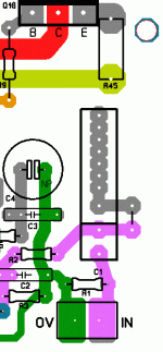
I notice a small error on the new layout: C1's furthest pad is not connected.
That is on purpose. With a long , large poly ... you would drill the hole , put the long lead through , bend it underneath .. solder it. This is to avoid having a "antenna" of a long trace for those that just use a 5mm wima.
I will try to refine C1's layout , regardless.
T93YB -
T93YB 25K 10% datasheet
No problem.
OS
And one my small suggestion rather stupid can you just add another pin for trimmers which not in line like Vishay T93YB type.
Here it is....
Universal large input cap trace w/jumper. Fixed !
Staggered 3 pin 2.5mm lead spacing / or inline 2.5mm trimmer pads. Fixed !
Broader sourcing is a asset for this project.
OS
Attachments
Bias set?
Yes , 22mv between these TP's would give you 50mA per OP device. You could probe between either TP 1/2 and the "OV tp" for 11mv , as well.
OS
Yes , 22mv between these TP's would give you 50mA per OP device. You could probe between either TP 1/2 and the "OV tp" for 11mv , as well.
OS
This is to low. You should target voltage no current according to Self.
dado
The last review before submitting (please help)
I am old , only have one set of eyes , no one in my house or neighborhood could possibly help (they know not what they see )
)
So , please look over this color draft of the project.
RED = +60V /positive rail
BLUE= - 60V /negative rail
GREEN = earth and signal ground
YELLOW = (dark yellow) - output trace / NFB
orange = positive OP stage drive
light blue = negative OP stage drive
pink = non-inverted small signal path to VAS
Reprinted , all devices have ample "real estate" (clearance) , all power semi's can be easily accessed with a screwdriver. Screenprint will show sections of circuit (LTP , cascode/CM , VAS, Vbe) for curious new builders .
.
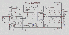
For convenience , the final schematic is also below.
OS
I am old , only have one set of eyes , no one in my house or neighborhood could possibly help (they know not what they see
So , please look over this color draft of the project.
RED = +60V /positive rail
BLUE= - 60V /negative rail
GREEN = earth and signal ground
YELLOW = (dark yellow) - output trace / NFB
orange = positive OP stage drive
light blue = negative OP stage drive
pink = non-inverted small signal path to VAS
Reprinted , all devices have ample "real estate" (clearance) , all power semi's can be easily accessed with a screwdriver. Screenprint will show sections of circuit (LTP , cascode/CM , VAS, Vbe) for curious new builders
For convenience , the final schematic is also below.
OS
Attachments
Last edited:
Sorry, maybe I missed something: there is a zener diode mark in schema (D3, near R18), that my eyes can't get to see. Please, help.
That is a "planned" thing as well. Some would like to reference the cascode with a 12-15v zener or even an led string (3 smd blues/5 smd reds - it works - done it.) So it can be either D3 OR R18 .... this will be in the "Cascode/current mirror"
section of the "Options" text.
OS
For convenience , the final schematic is also below.
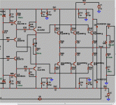
The only problem with OS are some LTPs and VASs drawn upside down...
Very curious about the sound.

The only problem with OS are some LTPs and VASs drawn upside down...
Very curious about the sound.
Sound_Buster, the time has come for you to start a brazilian group to build OS´s amps! His job deservers our efforts. I think that we could help develop this project if many of us built this beauty!
It makes a long time I wish to do this, but it seems there´s never "a final schematic"!!

(sorry for this last statement, but I am no researcher or developer... I could only build it "as is", and evaluate the sonics and overall performance.)
Last edited:
For this topology , this is Final.
#1 - between the layout and the circuit , the theoretical THD can not get any lower at this amps low to mid power levels (.38ppm !! 1k 1-2ppm @ 20k).
This is totally true at the VAS - running a class A Op stage , you would realistically get ppm performance.
#2 - The output stage WILL realistically add the most distortion depending on load + the quality of power supply. NFB +TMC will NOT cancel everything.
A triple OP or a well designed lateral might just better this amp.
#3 - the sound "quality" also might improve with the more advanced OP stage as well , but we want to keep this simple for the first time builders. A EF2 can be quite effective if designed right. The MJE15032/3 pair will form a colpitt's oscillator with the wrong base-stopper and a "crazy load" / abuse-clipping.
It is the driver that determines the OP stage's OLG and resulting stability.
Strange .... I found this out by accident by using my sanken 2sc3263/2sa1294 ...AS THE DRIVER PAIR.
Then I found this:
post #51 -
OPS
....which confirmed my suspicions on EF2 and 3 OP stage stability.
To generalize all this ,
You want the drivers to be faster than the OP's , as a few example's:
---- DRIVER / OUTPUT
2sc4793/2sa1837 /100mhz Ft -- njw0281/0302 /30mhz Ft (1-2 pair)
A+ - but low driver SOA.
----- DRIVER / OUTPUT
MJE15032/33 cob 200+ - 30mhz Ft --- njw0281/0302 /30mhz Ft
Durable , general purpose workhorse ... B+ (grade)
---- DRIVER / OUTPUT
2sc4793/2sa1837 /100mhz Ft --- 2sc3263/2sa1294/ cob 200 - 60mhz Ft
Better yet , this is the fastest EF2 for 8R loads , has the lowest THD. needs the lowest value "suckout" capacitor (.22- .47uF) and the lowest driver bias.
Fast , cool , and the OEM's love it (cheap)
----- DRIVER / OUTPUT
2sc3263/2sa1294/ Cob 200 - 60mhz Ft --- 4-6 pair njw0281/0302 / 30mhz Ft
This actually would be the VERY BEST EF2 , highest gain and current .. fast , too.
My latest- greatest is ( bd139/140 / 2sc3263/2sa1294 / 3 X njw0281/0302 )
used in a triple (below).
This DIYA amp with the below output stage would indeed break ground. But , it might be too imposing for some constructors.
Device choices WILL affect stability , durability , and maybe... the final "sound".
OS
#1 - between the layout and the circuit , the theoretical THD can not get any lower at this amps low to mid power levels (.38ppm !! 1k 1-2ppm @ 20k).
This is totally true at the VAS - running a class A Op stage , you would realistically get ppm performance.
#2 - The output stage WILL realistically add the most distortion depending on load + the quality of power supply. NFB +TMC will NOT cancel everything.
A triple OP or a well designed lateral might just better this amp.
#3 - the sound "quality" also might improve with the more advanced OP stage as well , but we want to keep this simple for the first time builders. A EF2 can be quite effective if designed right. The MJE15032/3 pair will form a colpitt's oscillator with the wrong base-stopper and a "crazy load" / abuse-clipping.
It is the driver that determines the OP stage's OLG and resulting stability.
Strange .... I found this out by accident by using my sanken 2sc3263/2sa1294 ...AS THE DRIVER PAIR.
Then I found this:
post #51 -
OPS
....which confirmed my suspicions on EF2 and 3 OP stage stability.
To generalize all this ,
You want the drivers to be faster than the OP's , as a few example's:
---- DRIVER / OUTPUT
2sc4793/2sa1837 /100mhz Ft -- njw0281/0302 /30mhz Ft (1-2 pair)
A+ - but low driver SOA.
----- DRIVER / OUTPUT
MJE15032/33 cob 200+ - 30mhz Ft --- njw0281/0302 /30mhz Ft
Durable , general purpose workhorse ... B+ (grade)
---- DRIVER / OUTPUT
2sc4793/2sa1837 /100mhz Ft --- 2sc3263/2sa1294/ cob 200 - 60mhz Ft
Better yet , this is the fastest EF2 for 8R loads , has the lowest THD. needs the lowest value "suckout" capacitor (.22- .47uF) and the lowest driver bias.
An externally hosted image should be here but it was not working when we last tested it.
Fast , cool , and the OEM's love it (cheap)
----- DRIVER / OUTPUT
2sc3263/2sa1294/ Cob 200 - 60mhz Ft --- 4-6 pair njw0281/0302 / 30mhz Ft
This actually would be the VERY BEST EF2 , highest gain and current .. fast , too.
My latest- greatest is ( bd139/140 / 2sc3263/2sa1294 / 3 X njw0281/0302 )
used in a triple (below).
This DIYA amp with the below output stage would indeed break ground. But , it might be too imposing for some constructors.
Device choices WILL affect stability , durability , and maybe... the final "sound".
OS
Attachments
This project started out as a request from DIYaudio to Ost to design an amplifier for the Community and to make the PCB available through the DIYaudio shop.Sound_Buster, the time has come for you to start a Brazilian group to build OS´s amps! His job deserves our efforts. I think that we could help develop this project if many of us built this beauty!
Suggestions to organise pirate Group Buy seems to defeat the intent.
It is the driver that determines the OP stage's OLG and resulting stability.
Strange ....
Although have built few amplifiers (only two...
What is the schedule for the boards appearing at DiyAudio Store?
sorry about commenting so late
the diff pair cascode resistive bias will compromise performance
a simple improvement is to use resistive bootstrap - add a R from the output to R19 in the ratio of the feedback resistors
I would still add a follower between the diff pair degen R and the cascode bias - the diff pair shouldn't be subject to resistive load or positive power supply noise injection at this point - check the psrr performance/look for ps ripple frequency sidebands - the filter for the front end is not that great for ps ripple frequencies
why no current clamp on the VAS - you already have the emitter degen R?
and I could (have) go on at some lenghth about TMC - a interesting criticism could be that the "single pole" "damped step response" of the global loop is in fact dangerous in a beginner's amp since the true stability margin is not reflected in the step response
Last edited:
- Home
- Amplifiers
- Solid State
- diyAB Amp - The "Honey Badger"


