Agreed copper would be even better. My old Nakamichi CA 5II had case that was shielded with copper foil inside. Some Microlab amps do have aluminium heatsink in between trafo and PCB with ICs good for shield effect but awful for convection. For a heatsink it is much better to be outside to let airflow go through it without obstacles otherwise noisy fans are required.By the way, you may consider that eddy currents are the reason why aluminium cases have a shielding effect and that you actually could rather profit from eddy currents in your heatsink.
Actually when electron gas is responsible for heat transfer in solid bodies they perform way better therefore copper and silver not only best for electric wires but excellent heat conductive materials as well. Launch vehicle nozzles are fabricated from copper allow. Next step would be moving substance itself like heat pipes or water/oil/liquid metal (some nuke reactors) pumping.
Like all other currents eddy currents need a closed path. By drilling holes or making slits in the right places, those paths are interrupted and eddy currents can either not flow at all or need to use a longer path with a higher impedance which dampens them. The same principle is used in transformers where stacks of isolated sheets are used instead of massive cores to avoid eddy currents.
By the way, you may consider that eddy currents are the reason why aluminium cases have a shielding effect and that you actually could rather profit from eddy currents in your heatsink.
Still, I would like to know how this works. So suppose I'm really stubborn
") and I want to fight Eddy currents anyway. Let's say I have a simple thick block of copper as my heatsink - where do I drill holes/slits in order to minimise the eddies?
and I want to fight Eddy currents anyway. Let's say I have a simple thick block of copper as my heatsink - where do I drill holes/slits in order to minimise the eddies?Let's say I have a simple thick block of copper as my heatsink - where do I drill holes/slits in order to minimise the eddies?
First you would have to find the direction of the magnetic flow that causes the eddy currents. They flow in a circle at a right angle around the magnetic flow, so you need to arrange the holes/slits so that they are in parallel to the magnetic flow to interrupt them. A massive block is the most unfavourable thing for that. In analogy to the transformer example you'd rather use copper sheets, insulating lacquered and stacked on top of each other. Here you run into the issue that the lacquer is adverse to the heatsinking. Then again, determining the direction of magnetic flow must already be a discouragingly difficult endeavour.
The currents through the traces inside the amp IC could induce them, if they were not layed out in a way that they canceled each other out inside the IC and if the audio currents were big enough and if the traces would run close enough to the heatsink. Fighting eddy currents in an amp heatsink is probably like taking a sledgehammer to crack a nut, but unle_leon's purpose was obviously to rule out all possible distortions in a cost/effort-no-issue way.
The best solution at this moment is tu use a heatpipe:
heatpipe cooler - C?utare Google
You can read here how it works:
Heat pipe - Wikipedia, the free encyclopedia
File:Heat Pipe Mechanism.png - Wikipedia, the free encyclopedia
They are already available separately or in different configurations, especially for cooling CPUs.
Another solution is to use a peltier element:
peltier cooler - C?utare Google
Peltier element problem is that it use a lot of power compared with heatpipe who do not consume any energy.
Of course is possible a combination of this two solutions.
With peltier element you can obtine a negative temperature but using a lot of power. At the same time it must dissipate a lot of heat generated by Peltier element.
The peltier cooler also has problems with condensation and dripping water, frost, etc. if the air is humid or the heat-producing item fails or loses power. Blow a fuse and after a while the cooler looks like an old freezer, covered with frost and ice, melting and dripping....
Where it IS good is in the cases where you can over-drive or over-clock a component (or extend its life) when it is cooled way below normal room temperatures.
Where it IS good is in the cases where you can over-drive or over-clock a component (or extend its life) when it is cooled way below normal room temperatures.
I'd have a look at the heat pipe options from companies like Berquist and Avvid, there are also phase change heatsinks that are very good. The phase change options (heat pipes) give the best results, and are used alot in areo/mill designs, where space, heatsinking area etc is often limited. Also having a thermal camera will give you some good feedback, but there not cheap.
http://www.edn.com/contents/images/11-WA1--Philippe_Sochoux.pdf
http://www.edn.com/contents/images/11-WA1--Philippe_Sochoux.pdf
A lot of PC cooling solutions do good jobs. PC heatsinks ususally take a different approach than DIY audio heatsinks. It seems to be the norm to use big fat chunks of aluminum to cool your amp, whilst in the PC realm of things, smaller heatpipe and thin finned coolers seem to be the norm. You can get more cooling in less space when you allow more surface area to radiate heat, or to be actively cooled by a fan. If you strapped a small DC computer fan to one of the PC heatsinks, you should have absolutely no problems with heat, even if you are absolutely pounding it.
Since I used to build a lot of PCs before I started getting into electronics, I like using computer heatsinks on my amps. They work well, provided you get one that fits your application.
You can also try one of those sealed-loops liquid cooling systems. You don't actually have to worry about filling the liquid up every so often, and then done leak. Corsair makes some decent ones. It would be more than your average heatsink, but it does work well, at least in PCs.
Newegg.com - CORSAIR CWCH60 Hydro Series H60 High Performance Liquid CPU Cooler
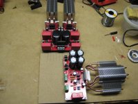
I attached the use of heatsinks in my own amp build. This is an old picture, but my camera isn't charged, so I can't photograph the new setup with them. This is just a mockup.
Since I used to build a lot of PCs before I started getting into electronics, I like using computer heatsinks on my amps. They work well, provided you get one that fits your application.
You can also try one of those sealed-loops liquid cooling systems. You don't actually have to worry about filling the liquid up every so often, and then done leak. Corsair makes some decent ones. It would be more than your average heatsink, but it does work well, at least in PCs.
Newegg.com - CORSAIR CWCH60 Hydro Series H60 High Performance Liquid CPU Cooler
I attached the use of heatsinks in my own amp build. This is an old picture, but my camera isn't charged, so I can't photograph the new setup with them. This is just a mockup.
Attachments
Last edited:
This thread belongs in the NerdAudio forums, not the DIYAudio Forums. Just Kidding
BTW, I REALLY LIKE the above post with the heatpipes on the chipamp!
Here's something simple I came up with (not built yet) that costs nothing, straight DIY.
IC Chip on Big Copper or Copper/Aluminum Hybrid CPU Heatsink (or heatpipe sink)
Coat the PCB, and chip leads with Waterproof Silicone Gel so water won't short it out.
Put Heatsink in Water Using a large plastic kitchen dish, tupperware, etc
Blow cooling fan on water surface.
Add water as it evaporates.
Simple, cheap, and keeps chip cool.
Last edited:
Without fans (which I currently rely on, but would like to avoid) we rely on convection from hot air rising. It certainly seems to me that the basic shape of most amplifiers is just wrong. We might not need tall finning, but certainly a lightweight tall insulated chimney atop our heat sinks would be a huge improvement.
I see some folks use chip amps with the isolated tabs, ( see image in post #55 ), which is double the thermal impedance. So right off the bat you need a 2x bigger HS or increased forced airflow and the fan noise.
You can get cheap performance gains by concentrating on reducing the impedance at the tab to HS interface. like no insulators, good clamps, special grease, etc, ( note w/o an insulator on the tab, the HS can be electrically live, so unusual precautions needed there, not a huge problem for DIY chassis design.) For more exotic uses decrease the chip to tab impedance as well see military hardware examples like SMPS hybrids and cold water plates.
You can get cheap performance gains by concentrating on reducing the impedance at the tab to HS interface. like no insulators, good clamps, special grease, etc, ( note w/o an insulator on the tab, the HS can be electrically live, so unusual precautions needed there, not a huge problem for DIY chassis design.) For more exotic uses decrease the chip to tab impedance as well see military hardware examples like SMPS hybrids and cold water plates.
- Status
- This old topic is closed. If you want to reopen this topic, contact a moderator using the "Report Post" button.
- Home
- Amplifiers
- Chip Amps
- Improving heat transfer of ICs