Fortunately, there is more than one way to skin a cat.
Cheers,
Bob
Bob,
I hope you are not speaking from experience! Isn't it interesting how we often ignore what cliches really mean?
ES

(in particular, as my drawers are still filled with J72/K147/J73/K146/J74/K170/J75/K240/J109/K389)
You really need to read a copy of Linear Audio Vol. 0!
my drawers are still filled with J72/K147/J73/K146/J74/K170/J75/K240/J109/K389
Doesn't that get itchy?
Mr Simon,
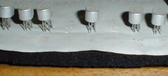
over the last 2 decades i've glued A4 size paper sheets on 1/4" layer foam, before the accupuncture session routines.
Your notebook note has been noticed and noted (page 162-163, no?)
Excellent!

What is 'amusing' Bonsai, is that I designed the input topology that YOU use back in 1968, in my first 'comp-diff' power amp. The next year, 1969, I built a 2KW, four quadrant, current output version while employed at the Ampex Research Department, YET I evolved to the 'comp diff jfet' input stage mentioned recently here, a couple of years later. Do you know why? I am the 'father' of both designs, yet I have not made a circuit similar to your power amp since 1973, a long time ago. Could there be some 'advantage' to jfets? Of course there is, and now I am stuck with 1000's of bipolar semiconductors that I don't know what to do with. I would hate to just throw or give them away. Any suggestions?
SY's right though, accupuncture is really itchy.
(2 pictures and only 25 lines, impossible to resist.Balloon texts on the next article would be grand)
An interesting variation! I got rid of over 200 little plastic drawers by putting the pages in a 3 ring binder. I use the side of the foam for transistors, by placing strips over divider that has been through my printer for labeling.
What is 'amusing' Bonsai, is that I designed the input topology that YOU use back in 1968, in my first 'comp-diff' power amp. The next year, 1969, I built a 2KW, four quadrant, current output version while employed at the Ampex Research Department, YET I evolved to the 'comp diff jfet' input stage mentioned recently here, a couple of years later. Do you know why? I am the 'father' of both designs, yet I have not made a circuit similar to your power amp since 1973, a long time ago. Could there be some 'advantage' to jfets? Of course there is, and now I am stuck with 1000's of bipolar semiconductors that I don't know what to do with. I would hate to just throw or give them away. Any suggestions?
I know you are the originator John and it's a very fine topology. That's why I use it rather than some of the single ended types.
However, as I have said many times before on this forum, there are many fine amplifiers that do not use the FBS topology ( and in Stereophiles A list), so although you and I like FBS, and you say it has to be done with JFETs, clearly this is not the only route to amplifier Nirvana. I guess all I am saying is I am a pragmatist on the subject.
Anyway, I don't want to get into an argument with you. Your amplifiers speak for you and you should be respected for that.
Nice input stage Bob BTW - I have your book and already took a close look at that one. Might be one way to get around the scarcity of p-channel devices.
Jacco, the transformer cost me $500. Was it worth it? Hell yes and when I build my new amp I am going to do it again. My wife will get pissed off again though.
Bonsai, you may be very happy with your power amp. Good, you are right, people who invest time and effort into their designs appreciate them more.
However, there are certain advantages to jfet input design that you are missing, but that's OK with me. However 5 uH for an output inductor? 2 uH should be enough, from my experience.
However, there are certain advantages to jfet input design that you are missing, but that's OK with me. However 5 uH for an output inductor? 2 uH should be enough, from my experience.
Bonsai, you may be very happy with your power amp. Good, you are right, people who invest time and effort into their designs appreciate them more.
However, there are certain advantages to jfet input design that you are missing, but that's OK with me. However 5 uH for an output inductor? 2 uH should be enough, from my experience.
The circuit diagram says 5uH, but I rewound it for 2uH. I am using 21193/21194 output devices which are slow, so I have erred on the safe side here with compensation and the output inductor. The new stuff I am working on uses fast devices, so I will shoot for 1uH.
JFET's - I don't disagree that they do some things very well.
Nice input stage Bob BTW - I have your book and already took a close look at that one. Might be one way to get around the scarcity of p-channel devices.
Hi Bonsai,
Thanks for the compliment on the input stage.
There are two additional things worth mentioning. The common mode signal that is generated to drive the bases of the pnp common-base stage can also be level-shifted and used to bootstrap the bases of the top npn cascode transistors.
If one wants to ge a little crazy, the stage can be extended to be a JFET cascomp, similar to the BJT complementary cascomp described in Figure 25.12 in my book.
Cheers,
Bob
The complementary JFET input stage popularized by John is indeed elegant, but the lack of suitable complementary dual JFETs makes it difficult and expensive to put into products these days. It also requires good JFET matching to achieve its best performance. Fortunately, there is more than one way to skin a cat.
The circuit below is after Figure 7.13 in my book Designing Audio Power Amplifiers. It achieves the same functionality while using only N-channel JFETs. Q3 and Q4 are common-base stages that harvest the source currents of input JFETs Q1 and Q2. R1 and R2 provide source degeneration. The key to circuit operation is to drive the bases of Q3 and Q4 with an accurate replica of the common mode voltage of the input signal. This is accomplished by emitter followers Q5 and Q6 which sum the source voltages of Q1 and Q2 to drive the bases of Q3 and Q4 with the replica common mode signal. Current source I1 conveniently sets the stage operating currents by creating a DC voltage drop across R3 and R4 that is also forced across source degeneration resistors R1 and R2.
Cascodes Q7 and Q8 complete the IPS cell, resulting in cascode outputs to both the top and bottom loads of the cell. Load resistors R5-R8 are just illustrative, and the stage can be used as the IPS in many different complementary architectures, including folded cascodes. The circuit is equally suitable for use in line-level stages and power amplifier input stages.
It is notable that, with the exception of the small base currents of Q5 and Q6, the same current of each input transistor is conveyed to the top and bottom loads, making the transconductance to the top and bottom essentially the same. This is sometimes not the case with the classical complementary JFET IPS because the gm of the P and N-channel JFETs may not be the same for the same operating current.
In fairness to the classic JFET complementary IPS, this stage will often have slightly higher noise, since the classic design effectively places two pairs of input JFETs in parallel and can operate with no source degeneration if so desired. The source degeneration shown in this circuit can of course be made smaller.
Cheers,
Bob
Your Fig. 7.13 is very neat stuff, Bob. We chatted via email how I had done a similar trick back in 2003. It is quite effective, and as you note, completely does away for any need for matched complementary JFETs... a near impossibility these days. I also shared my notes on that 2003 project with John Curl. But Bob Cordell is the one who brought this useful idea to print in his power amp book.
Irony (1): This exact topology could easily be used within *today's* IC op amps, for example the AD825 which has a pair of input JFETs with both drains going right to the rails (i.e., all the "topside" dynamic current is wasted). I even wrote to one IC company about it (with no response whatsoever).
Irony (2): Similarly, the same thing would also apply to the LM301/301A and also to the uA741 (the latter with an alternate input stage bias loop).
Regards to all,
Walt Jung
- Status
- Not open for further replies.
- Home
- Member Areas
- The Lounge
- John Curl's Blowtorch preamplifier part II