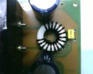
This afternoon, I bought around a metre of 18 SWG (1.293 mm dia) and made up the choke. It looks just fitting into the window.
Workhorse was right about the number of turns (17) and I was never wrong about the wire guage and window utilisation factor of 50%.
Please see picture.
Workhorse was right about the number of turns (17) and I was never wrong about the wire guage and window utilisation factor of 50%.
Please see picture.
Attachments
Last edited:
I connected the power supply (+/-38V) and see that my gate drive power supply is only around 8V. I have a 12V regulator running between -17.7V and COM(-38V). Is there any problem with the regulator ckt?
I expect -17.7 to be regulated to -24V. But I see only -30V (not -24) at output. Pls see picture in #77 and pls read
1) -17.7 instead of -21V
2) 7812 instead of 7815
3) -38V instead of -45V
Please help. Thanks.
I expect -17.7 to be regulated to -24V. But I see only -30V (not -24) at output. Pls see picture in #77 and pls read
1) -17.7 instead of -21V
2) 7812 instead of 7815
3) -38V instead of -45V
Please help. Thanks.
Last edited:
But I see only -30V (not -24) at output.
Oscillation?
Hi friends,
I have managed to get a discrete power supply working for the gate drive.
Level shift is working and so is the 4070. Unfortunately, I do not have access to a scope.Is it possible to test the amplifier (oscillation etc.) without a scope...
Just apply some sound to the input.
I built a semi discrete class d amp too.
The only awkward stage was the level translator into the 2113 wasnt quite right. I had to add a diode to plus volts to stop the 4070 latching up.
Hi friends,
I made my first test on the amplifier and here are the results for no load and shorted input.
1) MOSFETs cool, but choke is very hot.
2) The choke sizzles like a transformer, whenever I try making measurements with the meter.
3) However the supplies measured +/-32V (which is 38V w/o the IR2110).
What could be wrong? I dont have a scope.
Last edited:
I tested the amp again, but this time the choke is cool and the MOSFETS are cold. When I tried measuring the b/strap supply, the MOSFETS suddenly became warmer and warmer.
As of now, the power supply is completely low (below +/-1 volt) when the amplifier is connected (which is +/-38V otherwise) and both MOSFETs are conducting both ways, even without the gating signals, with a 1 ohm resistance (by the meter).
Have I blown the MOSFETs? If yes, how ? I have not yet connected a load.
Please help.
I will try my best to get an oscilloscope but i may not be able to get one thats beyond 30MHz or so.
I tested the amp again, but this time the choke is cool and the MOSFETS areHave I blown the MOSFETs? If yes, how ? I have not yet connected a load.
Please help.
I will try my best to get an oscilloscope but i may not be able to get one thats beyond 30MHz or so.
Sounds like the mosfets have blown, check with a multimeter between D-S.
If it shows a short then they are blown.
I tested the amp again, but this time the choke is cool and the MOSFETS are cold. When I tried measuring the b/strap supply, the MOSFETS suddenly became warmer and warmer.
As of now, the power supply is completely low (below +/-1 volt) when the amplifier is connected (which is +/-38V otherwise) and both MOSFETs are conducting both ways, even without the gating signals, with a 1 ohm resistance (by the meter).
Have I blown the MOSFETs? If yes, how ? I have not yet connected a load.
Please help.
I will try my best to get an oscilloscope but i may not be able to get one thats beyond 30MHz or so.
Hello newvirus,
If I were you, I will not connect the feedback loop before you find everything is okay, especially with a new design. I will first disconnect the MOSFET, drive an AC signal (using computer sound card playing sine wave) into the comparator. Even without a scope but a DMM, you can still check whether there is AC output from comparator, then check level shifter, then logic input to IR2110. Short Vs of IR2110 to COM. Check both low side and high side output of IR2110. If everything okay, I will then disconnect VS and COM and connect the MOSFET. Try drive the AC signal frequency as high as possible, otherwise the bootstrap power supply for the high side may not work. Measure the current drawn by the MOSFET and temperature to guess whether there is shoot through. Check MOSFET output and inductor for AC. If everything is okay, I will then close the feedback loop.
With a scope and a siggen, it will be a lot easier.
Good luck.
Last edited:
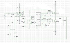
HiMy circuit is LM319=>BC556+2 x 2.7k level shift=>CD4070=>IR2110=>IRF540=>
TN23/14/7,17T (22uH)+680nF.
Finally.. I hear a DIY that is using the right components (INSTEAD LM339). if you want, you can replace with faster HFE4070 Philips cd4070.
Regards
Roberto
Hi,
CD4070 was blown. Managed an oscillation at 250kHz with IRF530s.
There is visible distortion in the output when maxed (rail-rail) even without load.
Small DC offset(<1V) at output.
Square wave for 0V input has extra couple of short pulses in every cycle.
Idle current (+/- 32V) is 100mA (negative inlcuding GD regulator) and 50mA (positive).
IRF530s and choke warm and I hear faint sound when playing 10kHz even w/o speaker.
If I change to IRF540N or IRFB5615, will the oscillation frequency get affected much?
Circuit attached.
Attachments
Last edited:
- Status
- This old topic is closed. If you want to reopen this topic, contact a moderator using the "Report Post" button.
- Home
- Amplifiers
- Class D
- Ucd for s/woofer appln