Well, that's the problem with the paradigm of running a high current through the ribbon! The basic issue is that even the lightest air-stable metals are really dense compared to most polymers. Make the metal thick enough to get decent conductivity and you end up having the metal dominate the mechanical characteristics, especially mass. Laminating is generally not the issue- that's stuff that the flex circuit people worked out years ago.
Could one directly make the plastic film conductive? Sure, films can be loaded with all sorts of conductive fillers, but a realistically sized ribbon would still have a lower limit of 20-30 ohms- the loaded polymers just aren't conductive enough.
The ribbon driver in this model is, I think, a dinosaur. Electrostatics or, even better, active polymers (e.g., poled PVDF structures) are the way to go for a low-mass line source.
I haven't tried stretch-oriented doped polyacetylene in a ribbon yet...
well it is nice to get thin and light as possible.
but as everyone has noted the tradeoff is always power handling vs mass for the traces.
so, the place to look is at the magnetic structure and maximize the flux in the gap?
overall, it seems to me that there are light enough materials being currently used in commercial ribbons... differences in implementation clearly make the difference between modest quality and very high quality results, given the few choices in film/foil and similar film/foil combos in various drivers with various results?
...so it seems to me that the place to concentrate effort is in the implementation details, not the film/foil so much?
that's my thinking on the subject. so far
_-_-bear
PS. I am interested to *know* what companies are making etched & finished film foil combos for commercially sold drivers - anyone *know* anything about this??
I know this is a very old thread but I wanted to ask if anyone has tried etching a metallized film to make the conductors, for a planar magnetic diaphram. And I have some more-or-less random questions about diaphrams and conductors for planar magnetic speakers.
And is there anyone with more thoughts about the best type of film to use?
Here is a link with descriptions of some of the properties of many types of films:
Engineered Films
(I noticed that Polymethylpentene is listed as having "excellent acoustic properties".)
And here are some interesting articles, including one link to a bunch of planar speaker patents (I had no idea that Nelson Pass also has a bunch of them.):
http://www.integracoustics.com/MUG/MUG/articles/
And here is a really-interesting article about planar speaker technology:
http://72.52.208.92/~gbpprorg/mil/mindcontrol/military+white+paper+MAD.pdf
And, by the way, here's a whole bunch of metallized polypropylene capacitor film for sale on ebay, cheap (maybe useful for the ribbon folks):
Aurora Zinc Metallized Polypro Capacitor Film - 12 Roll - eBay (item 360335999370 end time Jan-20-11 10:42:55 PST)
And some Kapton tape that looks metallized:
Kapton tape High Temperature 1" 25mm X 100ft for BGA IC - eBay (item 170378958978 end time Jan-26-11 01:02:54 PST)
And if one did use aluminum wire glued on a plain film, would this type work (.035 or .030-inch diameter)?:
8 1 lb Spool .035" 4043 Aluminum Mig Weld Welding Wire - eBay (item 140341177523 end time Feb-12-11 12:04:57 PST)
Can femm be used to calculate/simulate how much force would be produced on a given length of a given set of conductors with specified shapes/sizes/spacings with a particular magnet configuration, for a given current? (Or can it at least be used to compare configurations?)
Does anyone know of a "flexible diaphram" simulator that could simulate the dynamic mechanical behaviors of a diaphram, hopefully with easy-to-implement multiple line-shaped forcing functions, flexible handling of boundary (edge) conditions, easy diaphram material specification and easy-to-do "added or removed material" regions (e.g. foil/glue, wires/glue, tape, etched areas), and aerodynamic effects? (I know, it's probably WAY too much to ask. Maybe I'll have to re-read my old Calculus of Variations book...)
Anyway, I think it would be great to be able to etch the conductors into large sheets of a metallized film, in order to make planar magnetic speakers, especially if that could give better performance than gluing on foil or wires. (Aside: But what about SEWING or weaving the wires into some material that could then still stay strong-enough?)
And I think it would also be great to be able to have the means to predict the mechanical/electrodynamic behavior and performance, so that some actual engineering design work and maybe even optimization could be done BEFORE acquiring materials (and to avoid embarking on a too-long voyage of half-blind experimentation).
Any information or ideas will be greatly appreciated.
Cheers,
Tom
Last edited:
I did a bit of research on this subject awhile back. Here's some of what I found:
For raw film:
Film Foil Laminates
or:
Sheldahl: flexible printed circuits flex circuit materials
for prefabricated custom parts:
Bulletin 1370A Flex Circuits and Metalized Film
Photo Etched Precision Parts - EMI Shielding - Flexible Circuits by Tech-Etch
If you persue this, I would be interested to know what you find out.
Good luck!
Keith
Thanks, Keith.
Not much to report yet.
I've got a small number (48) of neodymium magnets, now (2" x 1/2" x 1/8"), just for testing. Wow they are very strong. N42 or N45 strength; can't remember.
I have ordered a DC Gaussmeter with a directional probe. I hope it has the proper range and resolution. Its resolution is 0.1 milliTesla (= 1 Gauss). It has ranges for 200 mT (2000 Gauss) and 2000 mT (20000 Gauss).
I have been researching metallized films and plain metal foils.
It's been going slowly beause I have had to travel for work a few times and have also worked some weekends, as well as staying late at work a lot of the time. (I actually love my job and can't wait to get up and go to work every day.)
For those of you who use metal tape, check out this place:
Home - The Tape Depot - TheTapeDepot.com - The One and Only Tape Superstore. We carry Adhesive Tape, ATG Tape, Conspicuity Tape, Copper Tape, Duct Tape, Camo Tape, Carton Sealing Tape, Double Coated Tape, DOT Tape, Electrical Tape, Floor Tape, Foil T
I ordered a couple of things from ebay, just to play with: a roll of 0.030-inch aluminum wire, and a roll of metallized mylar.
I'll report back when I've done more.
Cheers,
Tom
Hi bandsei,
I will measure the resistance of the metal on the mylar after I receive it. I don't know what kind it is, at all, yet. If it's like the metalized Nylon that balloons are now made of, then it might be too high. I assumed that I would probably need to find exactly the right film and metallization, eventually, but wanted something to play with.
I received my digital "DC Teslameter", today ($155 USD new on ebay, from China). Tried it very briefly, before reading the manual. Orienting the narrow flat probe tip one way gives positive readings near one pole of a magnet and twisting the probe tip axially by 180 degress gives a negative reading of the same amplitude. Carefully aligning it vertically over the magnet gave a reading of zero. When horizontally aligned (i.e. parallel to magnet pole face), I was able to get the probe tip very near to (almost touching) the surface of a magnet before the reading went off-scale on the 0-to-200 mT range.
Placing the tip (vertically aligned) between two opposite-polarity-up magnets stuck to a piece of teflon-coated steel with holes in it (a pizza pan), I could see that the strongest field, halfway between the magnets and parallel to the steel plate (probe tip vertically aligned), was about level with the tops of the magnets. And I see that if the magnets are about 17 mm apart, the field in the center, level with their tops, is about 70 mT. But if I move them to be 12 mm apart instead of 17 mm, then I can get the same 70 mT at a distance of around 5mm (or maybe even 10 mm) above the plane of their surfaces (still centered between them). I didn't measure the height when I did that so it might be anywhere in there but it was significant. I will do real experiments at a later date. I also saw that if I carefully aligned the tip to be horizontal, when centered between the magnets, the measurement was zero, i.e. no vertical component, as expected.
If I make a little mount and positioner for this probe, I should be able to measure both the angle and the strength of the field, at any point. So it seems like I should be able to eventually figure out the most efficient magnet and conductor positioning scheme, and will also be able to know the absolute field-strength values. This meter seems like it should be a very helpful tool.
Cheers,
Tom
Last edited:
Hi Paradise_Ice
Dupont Mylar and Kaladex Polyester films, and Dupont Kapton Polyimide film are probably the most commonly used materials for planar and ribbon speakers.
Dupont Mylar has a Glass Transistion temperature Tg of 80 C
Dupont Kaladex has a Glass Transistion temperature Tg of 122 C
Dupont Kapton has a Glass Transistion temperature Tg of 360 C
Mylar can be found down to 2 microns in thickness, and 2.5, 3.6, and 5.0 micron mylar is pretty easy to find. The low Tg makes it a poor choice for high power metal-film laminates
Kaladex is harder to find below 7.6 micron thickness. Many new planar and ribbon speakers have converted from mylar to Kaladex films for the higher Tg.
Mylar and Kaladex are pretty "quiet" when you vibrate them.
Kapton is easy to get at 7.6 micron. 3.8 micron is also made by Dupont, but you may have to go directly to Dupont for purchase. Kapton's high Tg and melting point of over 400 C make it a very good material for high power planar and ribbon speakers. Kapton is also a good substrate for sputtering metals like Aluminum or copper. Many flexible PC boards use Kapton, as it is safe to solder to without special materials.
Kapton is a little "noisy" when you vibrate it.
There are a wider range of adhesives for Mylar/Kaladex than for Kapton.
mylar 1360 kg/m3
kapton 1535 kg/m3
Aluinum 2700 kg/m3
Just thinking to make new bassribbons for my Duettas, anyone know what should the right thickness be for Kapton? Found this while surfing -> http://www.kptape.com/index.php/product/Polyimide(Kapton)%20Film.html
They sell two thickness...2.5um amd 5um...with or without siliconeglue. 50m long 0,50m wide package would cost 100 euros including shipping...
kapton tape items - Get great deals on Business Industrial, Toys Hobbies items on eBay.com!
kapton copper items - Get great deals on Business Industrial, Electronics items on eBay.com!
The Tape Depot - TheTapeDepot.com - The One and Only Tape Superstore. We carry Adhesive Tape, ATG Tape, Conspicuity Tape, Copper Tape, Duct Tape, Camo Tape, Carton Sealing Tape, Double Coated Tape, DOT Tape, Electrical Tape, Floor Tape, Foil Tape, Ga
LIST OF PLASTICS FROM COMPLEX PLASTICS 1-888-PLASTIK 1-800-363-2870 SUPPLIER OF INDUSTRIAL PLASTIC MATERIALS
Kapton (and similar polyimides like Upilex) has great high temperature performance. Perfect if you want to solder on it or do a high temperature metallization. But... it is VERY "crinkly" sounding (think hard candy cellophane wrapping compared to kitchen wrap) and its tear propagation resistance is lamentable. Moisture uptake is also quite large. It's used a lot for applications where copper needs to be laminated and etched (e.g., flex circuits).
The issue with using metallized polyester is current-handling, which is not great. The metallization is almost always aluminum. It may be possible to get some polyester with a heavier metallization than normal and using a different (less oxidizable) metal.
The issue with using metallized polyester is current-handling, which is not great. The metallization is almost always aluminum. It may be possible to get some polyester with a heavier metallization than normal and using a different (less oxidizable) metal.
What would be the best to fix the magnets ? A perforated steel foil or several squared steel sections in contact all together ? Are they also glued or just fixed by the magnetic field on the steel support ?
Most of the DIY PMD projects have used magnets of less than 5 mm thick and 10 mm width with 10 mm gaps. Any comment on these parameters ?
Most of the DIY PMD projects have used magnets of less than 5 mm thick and 10 mm width with 10 mm gaps. Any comment on these parameters ?

What would be the best to fix the magnets ? A perforated steel foil or several squared steel sections in contact all together ? Are they also glued or just fixed by the magnetic field on the steel support ?
A PUSH-PULL motor design will produce the largest Xmax and the lowest distortion. Apogee Bass panels, and most Magnapan bass panels are a single sided motor with magnets glued to just one perforated steel frame. I think the Magnepan model 20 is a push-pull design.
Emininent Technology builds a steel frame to hold the magnets that form a push-pull motor. This design should produce the lowest distortion for a bass panel. (pic)
You will need to glue or clamp the magnets onto the frame. A few hours of FEMM modeling will help you decide the magnet strength and physical size.
For dipole bass, I personally think you will get better and more bass from a line array of high Qts large diameter woofers. AE Speakers has the Lambda IB15 that has good specs for dipole use, and Goldwood has a low cost 18" woofer with a Qts~1 that MJK has tested for his H-frame dipoles.
Attachments
Just thinking to make new bassribbons for my Duettas, anyone know what should the right thickness be for Kapton?
Hi Red,
FROM WHAT I HAVE READ, and owning 4 Apogee speakers, Apogee purchased 7.6u Kapton with a "thick " aluminum over the entire film. Thinner 2.5um - 3.8um Kaptour would be superior. Apogee manufacturing then used a simple straight edge and cutting tool that "lifted and cut out" several horizontal slivers to create one continuous serpentine BASS resistor on the kapton fillm. At this point manufacturing "corrugated" the full panel to add horizontal rigity to the AL ribbon. The Full Range has a 2ohm bass panel serpentine resistor. An Eagle 7B amp can put 1400 watts into this 2 ohm panel with a 120 Hz bridged power supply.... ultimate deeeeep Bass from a 7' x 2' woofer area.
Jason Bloom at Apogee was a genius. He understood the need to reduce panel resonance, and understood that only true steel springs could provide constant force over decades of use. The Apogee Kapton Bass films were clamped into a 2D wooden frame that used multiple adjustable steel springs as the "surround". The trapozial shape of the bass panel and variable spring tuning removed any single resonance.
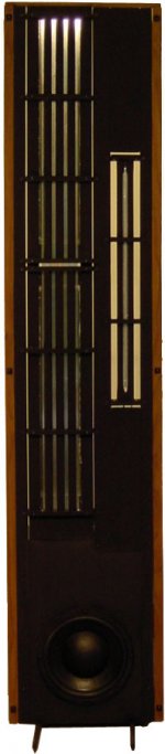
With 2011 technology, I think the ultimate linesource speaker would use a true ribbon midrange and tweeter, but use a line array of 15" or 18" high Qts woofers for bass. The bass would be mounted onto a physically separate assembly to avoid vibrating the M+T.. The mid+tweet ribbons could be toe'ed into the listener. The bass line array could be toe'ed toward the side walls to jiggle the room effects.
Personal Digital Cutter...
Ok, I am in. Has anyone considered using a Personal Digital Cutter such as: eCraft by Craftwell to do precision cutting of the mylar.
I was thinking of using it to cut both the Mylar and circuit.. Copper or Aluminum sheets..
Ok, I am in. Has anyone considered using a Personal Digital Cutter such as: eCraft by Craftwell to do precision cutting of the mylar.
I was thinking of using it to cut both the Mylar and circuit.. Copper or Aluminum sheets..
An externally hosted image should be here but it was not working when we last tested it.
magnetic calculator program
Hi there: You can also do some of this by simulation using the magnetics calculator on the K & J Magnetics web site as a starting point for your testing. How do you decide what magnetic field strength is required for a selected width of aluminum tape? ...regards Michael
I will measure the resistance of the metal on the mylar..... If I make a little mount and positioner for this probe, I should be able to measure both the angle and the strength of the field, at any point. This meter seems like it should be a very helpful tool.
Cheers,Tom
Hi there: You can also do some of this by simulation using the magnetics calculator on the K & J Magnetics web site as a starting point for your testing. How do you decide what magnetic field strength is required for a selected width of aluminum tape? ...regards Michael
With 2011 technology, I think the ultimate linesource speaker would use a true ribbon midrange and tweeter, but use a line array of 15" or 18" high Qts woofers for bass. The bass would be mounted onto a physically separate assembly to avoid vibrating the M+T.. The mid+tweet ribbons could be toe'ed into the listener. The bass line array could be toe'ed toward the side walls to jiggle the room effects.
funny this kinda sounds like a Carver speaker....
not nockin ribbons, I love them....
- Status
- This old topic is closed. If you want to reopen this topic, contact a moderator using the "Report Post" button.
- Home
- Loudspeakers
- Planars & Exotics
- Film laminate for planar driver