\Or this is cheaper and a newer design for a packaged system: Holzworth - Analyzers
Hello Demian,
Sorry for the late reply. For some reason I don't get notified regularly about postings to this thread. Must be a communist plot...
I have never heard of Holzworth. It's funny that they are right here in Boulder. Of course the NBS Time and Frequency Division (now NIST) has been in Boulder for over 40 years. Last year I found this company:
Symmetricom: Phase Noise and Allan Deviation Test Sets
They have been bought by a Silicon Valley outfit, but the founder and designer still lives in Boulder. I called him up and spoke with him for a while. He was actually the entire NBS lab director for while but hated the paperwork and demoted himself to division director.
Anyway he invented an incredible measuring tool for phase noise. Much better performance than the Agilent and only $18,000 to $35,000 depending on the configuration. But the problem is that it only measures sine waves.
That's nice and all. There are a lot of advantages to using sine waves for things. But all of the converter chips I know of use square waves for their clocks. So I decided to pass on that one. I guess I'll give the guys at Holzworth a call and see what they have to say. It looks like they are still independents, so that makes it easier to talk to the right guy at least. I had to pull some good tricks to get connected with the guy from Symmetricon.
Actually the important info is the same whether its sine or square but the instruments tend to be designed to manage sine waves since the best oscillators are sine. You can filter the digital into a sine wave without removing the important part. After the mixer it may not matter. I will try the FM tuner trick with some very high quality oscillators I have. The phase noise increases with multiplication (harmonics) so it may become significant enough to measure. If so the best tuners ever are still cheaper that the cheapest commercial phase noise system.
I'm interested in what you learn from Holzworth, not that I can conceive of spending that kind of money at this stage. For what you are doing (and any audio company for that matter) the universal systems like the Symmetricom are probably overkill.
As far as I can see there are only 7 or 8 clock frequencies used all audio products. If you are qualifying an oscillator you need two samples and the double balanced mixer (and some effort calibrating it). Assuming the oscillators are identical the measured noise will be 3 dB higher than each oscillator. A bad oscillator will be easy to spot.
This is getting a little far from Blowtorch stuff but its quite interesting. The TimeNuts Time-Nuts -- Precise Time and Frequency for Amateurs are as wacko as us audio nuts with clocks whose inaccuracy is below human perception over a human lifetime. . .
Phase Noise Analyzers
Yeah, I have some friends that do this kind of stuff for a living. They always say the same exact stuff you are saying. "Just get two calibrated oscillators and mixer. Then send the result to a double down-mixer and use the upper sideband with a good spectrum analyzer. You might have to calibrate it...."
I get lost after the first two words. I just want a box I can hook up and press a button to get the graph. It turns out the Symmetricom is designed exactly that way. But they make three models. The lower model only goes to 30 MHz, so if I ever wanted a 1024 Fs clock I would be SOL. And the top model doesn't include the calibrated clock. So I would have to get a clock that was characterized for phase noise. Then I would have to use LPFs to convert all of my signals to reasonable facsimiles of sine waves.
It's like saying to measure THD I need to build an analyzer from a kit and hand match all the resistors myself. I'm too old for that sh!t...
Maybe the Holzworth will be the ticket. The Symmetricom was really, really close. One problem is that they don't loan the Symmetricom out. The guy said that 90% of the time the people would solve their problem within a week and then they wouldn't buy the unit.
But why are there two serial coupled diodes?
From my analysis it sets the collector current of the middle transistor (its emitter connected to 250 and 330 resistors) to about 1 mA.

Last edited:
From my analysis it sets the collector current of the middle transistor (its emitter connected to 250 and 330 resistors) to about 1 mA.
Congrats you both got it. By changing the setpoint current and lower resistor you can make the switch trigger as low as .35 volts! Of course this is not quite a finished circuit. But the question had been raised how do you get a transistor to switch with Vbe less than .6 volts. At 0 Ic current Vbe is 0 and gain is 0. At 1ua Ic I can find some transistors with Vbe of <.4 volts but gain is only up to about 3 to 10!
Congrats you both got it. By changing the setpoint current and lower resistor you can make the switch trigger as low as .35 volts! Of course this is not quite a finished circuit. But the question had been raised how do you get a transistor to switch with Vbe less than .6 volts. At 0 Ic current Vbe is 0 and gain is 0. At 1ua Ic I can find some transistors with Vbe of <.4 volts but gain is only up to about 3 to 10!
I have a current mirror in a circuit that works down to 10pA.
I have a current mirror in a circuit that works down to 10pA.
Off the shelf transistors?
Off the shelf transistors?
No, but I bet you could turn up something.
No, but I bet you could turn up something.
Actually the current mirror is the commonly accepted method, but I was challenged to do something different.
What is interesting is last year the issue came up as to what is the gain of a bipolar at very low currents.
It seems that the manufacturers of discrete devices don't mention that what is sold as say an NPN may actually have a bit more there. I assume when you play at pa levels you are using a variation of the basic structure?
No, most of our NPN's and PNP's have nice looking Gummel plots down into the noise. There is a little beta rolloff. They don't sell many discretes with shallow bases and low breakdowns but you might be able to turn something up. BTW I've run Vbe's down to 50mV.
No, most of our NPN's and PNP's have nice looking Gummel plots down into the noise. There is a little beta rolloff. They don't sell many discretes with shallow bases and low breakdowns but you might be able to turn something up. BTW I've run Vbe's down to 50mV.
Really! Can I misquote you on this to stir up some heat and say you mentioned transistors that even at Ic =0 still have gain?
So folks no longer do an extra lightly doped region or so to control base spreading?
Well, it has been awhile since I contributed to this thread. I wish to thank Ed Simon for his interesting questions.
As many know, the Blowtorch did NOT use bipolar transistors, except in the IC's that were used in the servos, or the power supply regulators. Personally, I prefer FET's or tubes for their 'easier' sound quality, most probably because of the inherent 'linearity' of these devices, and subsequently the low % generation of higher order distortion.
On another subject, some people ask me whether there are any NEW Blowtorches, and sometimes, how many were made. For the record, we stopped making Blowtorches more than 5 years ago, after the death of my business partner, Bob Crump, who actually designed and built the Blowtorches, except for the electronics modules, which I fabricated here in California. Even before his demise, we had agreed to not make any more and about 45 were built, and sent to different locations in the USA and other countries. We never expect to make another Blowtorch preamp, but that does not make it obsolete or anything, it is just too difficult as we advance in age, to take on such a responsibility.
John.
This is what has been keeping me busy. Just got the prototype to work and updated the design and circuit layout.
ES
Differential temp sensor?
jan
Differential temp sensor?
jan
Getting there!
Getting there!
Well don't hold your tongue Simon, what is it? Not everyone on this board can read a schematic.
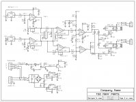
I see stereo LM34 Temp sensors, and and 2 relays at the output. So I'm guessing a Thermal protection circuit for an amp. Anything else would be off topic in this forum.
Well don't hold your tongue Simon, what is it? Not everyone on this board can read a schematic.
I see stereo LM34 Temp sensors, and and 2 relays at the output. So I'm guessing a Thermal protection circuit for an amp. Anything else would be off topic in this forum.
It is of course off topic. I apologize if this has caused you any concern. This is an item John and I discussed. Last year I went through where my energy costs were coming from and reduced my electric bill by 1/2. This was surprising to most here as all of the lighting is already high efficiency. However there was room for more improvement. In the winter the bill remained almost the same.
I showed this circuit as there are a number of good designers who participate and peer review is a good idea.
So from the start, The power supply is almost plain vanilla. A 24 VAC center tapped toroidal transformer (efficiency!) is fused on both legs as there is a center tap and a single fuse would not offer protection. C10 is really a superstition, to reduce EMI noise, who knows if it really does anything. The bridge is 4 x 1N4007 diodes as Mouser was clearing some out for 2 pennies each!. The filter caps into the regulator are both electrolytic (470 uf @ 63 V) and film bypass to prevent any HF instability. 470 uf yields about 100mv of ripple which is low enough the regulators clean it up to a level far better than is actually required. (63 volts because I had them!) I used the 1 amp version of the regulators so no heatsink is required.
The other input is from a U.S. standard thermostat. It should be compatible with anything from a simple mercury switch to fully electronic version. No matter what kind of output it will provide a voltage from 12 to 24 VAC to U3 an optoisolator. D12 is an on board indicator to show when the thermostat is "on." Although there is a common ground through the transformer center tap to maintain possible safety issues the isolator still provides reasonable protection against miss-wiring. Fuses F3 & F4 are actually .2A PTC resistors as mostly fault times are during hookup.
Q1 is a TIP darlington with internal pull up resistors. That gives two diode drops to turn on and plenty of gain. So when this part is active power is supplied to allow the relays to turn on. At DC driving inductors there doesn't seem to be oscillation so no capacitor was used base to collector.
There are two LM34 sensors. These provide 10mv per degree F. I like these better then the C version as there is more signal. As indicated the normal operating temperature is 100 Degrees F, the maximum should be 140. That allows a gain of around seven without worry about reaching the voltage rails. The LT1014 was chosen for low offset voltage. J3 allows remote monitoring of temperatures.
Now the excess parts... the other two sections of the quad opamp do exactly the same thing they subtract one sensed temperature from the other. Both R9 and R10 could go to either. This is a small bit of redundancy since the parts were there. If there is little difference (less than 10 degrees) the lower relay will turn on when called for by the thermostat circuit. If the temperature rises above that then the second relay turns on and the first goes off. If the difference continues to climb then both relays close.
As the relays are 24 volt they run from both rails. R28 and R33 make sure the gate voltage does not exceed the breakdown voltage. The diodes of course provide the switching logic. The comparator is not critical but it needs to be one that has open collector outputs.
Relays are used rather than triacs as they are rated at 30amps 240 VAC. The LEDs of course show the relay operation for diagnostics.
So what this does is when the thermostat calls for it the circuit starts a small blower or pump to allow the heating unit to operate at the temperature where it is most efficient. If the heat transfer is not enough (meaning it is not heating as fast as it can) then a second motor at twice the size is turned on by itself. It that still isn't enough then everything kicks in.
This should reduce costs by keeping the heat source at optimum temperature and using only enough electricity for the motors as required.
The audio use of course would be keeping a system at a constant temperature using a small quiet fan and a bit larger one. Constant temperature being a good thing as it allows the equipment to operate in a stable condition. For small systems a variable speed fan would work. On larger systems variable speed is expensive and lowers power factor.
The circuit can of course be simplified quite a bit. With a slight decrease in accuracy the opamps are just not needed. Running the sensors off the negative rail also will reduce parts count. As built there are no adjustments and all of the units I have built so far work to design goals.
I hope explaining design issues is of some value here.
- Status
- Not open for further replies.
- Home
- Member Areas
- The Lounge
- John Curl's Blowtorch preamplifier part II