Thanks Anonymous1. That's a good suggestion and worth a try.
From the graph it looks like it's about 5 - 10 ohms at 1 MHZ which is similar to a 1uH inductor. But it's also apparent it suffers similar saturation issues at high currents. I think the 3A rating is thermal, not magnetic. The graph shows the inductance is cut in half around 300 mA which is significantly worse than the 900 mA of the chip inductor I mentioned.
I'll throw a couple on my next parts buy along with the 0805 inductors. I can always measure them both.
The graph shows the inductance is cut in half around 300 mA which is significantly worse than the 900 mA of the chip inductor I mentioned.
Ah, the datasheet I was looking at didn't have that graph.
Here's the fair-rite part from above:
http://components.arrow.com/part/dataview/44065144S8846679N4455
http://components.arrow.com/part/dataview/44065144S8846679N4455
The DC values are the best estimate we have of relative magnetic saturation. None of these parts are spec'd at audio frequencies. Low frequency audio (which is usually where the most energy is in most music) should approximate DC as far as these tiny RF inductors are concerned. It's very different than say a steel core E-Lam audio transformer where the DC and AC values may be significantly different.
Because it's kind of "off label" (as the medical community would say) to be using 0805 chip inductors this way, I think the best solution is I can just test what happens under worst case high current audio conditions, as well as for any increase in THD, etc. I can use the 10 ohm QRV09 as the baseline.
Last edited:
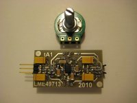
What's the LME49713 board for? Is it a group DIY project here somewhere?
It's just something I put together awhile back after making my LME49600 boards.
A simple non-inverting circuit with servo just like the LME49600 reference design, minus the buffers obviously. The 49713 can do 100mA so I figured the buffers would just muddy up whatever a CF op-amp would bring to the table.
the audio frequency concern is nonlinearity from the inductance modulation - probably only easily visible as IMD - for these parts audio is "DC bias" so a few 100 mA peak as you might see at bass frequency in a inefficient orthodynamic headphone could give very low level IMD with higher audio frequency signals
but since the inductive impedance is so low at even high audio frequencies I expect the numbers would be well below -60 dB @ 20 KHz even from inductors that show substantial L drop with real current levels - and the distortion products would fall with frequency for typical largely resistive impedance headphones
to minimize this possible distortion I could even suggest looking at cable bead cores - I think the principle is the physically largest core that just gives enough impedance will have the better DC bias performance in the same core material
long cylinders give better high frequency performance from less C between wire in/out than ring/toroid shapes
I'd guess larger center hole would mean more uniform magnetic path length - delaying onset of DC saturation - better for low level linearity but more abrupt saturation characteristic at large signal levels
they would just be slipped over the wires to the output connector
Steward 28B0375-100 has > 10x the material volume compared to the leaded 28L0138-10R
I also think you could go as low as 200-300 nH, as long as |Z| > ~10-20 Ohms above ~10 MHz
the lower values make air core single layer coil dimensions reasonable for putting in the wire between the pcb and the output connectors
but you should allow for lots of air space to any ferromagnetic material with the extended leakage field of the coil
Last edited:
I have an interesting story about DIY, board layouts, off board components etc. that might be somewhat applicable here (this is from one of my blog articles):
A friend built an amp and was raving how it was so detailed he could finally hear differences in RCA interconnect cables. I was skeptical so we measured it and found out it was unstable and ringing (partly oscillating) to varying degrees depending on the input cable capacitance. So his cables did indeed sound different because they caused the amp to produce different amounts of ultrasonic garbage! We traced the problem to a poor ground scheme for the input stage and jacks.
The funny (sad?) part of the story is he seemed disappointed once the grounding was fixed and the amp stopped oscillating. He thought he was onto something great. He heard the severe instability as being "different" and hence "better". It's funny (sad?) how misleading "designing by ear" can be with all the psychological biases that are typically present.
It's also worth noting he tested the above amp, while it was highly unstable, with RMAA and it passed with flying colors. The ultrasonic oscillations were well above the cutoff of any soundcard's anti-aliasing filter and hence were invisible to RMAA. And apparently the audible side effects were also not picked up by RMAA. That's just one of many reasons why I take RMAA measurements with several big grains of salt.
I can't stress enough how many designs/projects/DIY boards and even some commercial products I've measured had some serious problems related to the implementation like the example above. They use the right parts, the schematic is usually fine, but the devil is in the details--especially when you're working with parts that have response well into the megahertz RF range. Layout, for example, can be everything.
So in this case, the more that can be done on the PCB the better. That greatly increases the odds others will get the same performance and not have unexpected (and possibly non-obvious) problems like my friend with his amp. So I'd prefer to find an "on board" solution to the output inductor problem.
In audio power amps (for speakers) I know 0.5 uH - 5 uH is the typical range for output inductors and there is some debate over using ferrites for exactly the reasons JCX mentions. One reason I like the Taiyo part is they're shielded and should be less susceptible to electromagnetic coupling than a typical inductor. If it creates IMD it should show up in the "before" and "after" measurements--especially if I stress the amp to its current limits.
I don't know how much capacitance the TPA6120 needs to see at RF frequencies to become unstable, but anyone doing an inductor off board may need to avoid creating too much capacitance and/or coupling to the wrong places in the circuit degrading the stability.
@theAnonymous1, Have you tried RMAA yet? Within its limitations it can be fairly useful to at least provide some verification. Obviously the LME49xxx parts are better than any soundcard but at least RMAA will help spot many more serious problems that might not be readily audible. There are some tips here on avoiding lots of RMAA problems:
RightMark Audio Analyzer Blog Article
Like most of us, my free time is limited and I've got a backlog here of things to test as it is. I have a AMB Mini3 amp, FiiO E7 amp/DAC, the NG98MKII on the way, the QRV09 to build and test, and I'm overdue to measure some PC's and laptop headphone jack's as well. I'm trying to mostly stick to things with fairly broad appeal--at least for now.
looks like ~ 1" of pcb trace between the output and the connector block
over estimating trace width as 2 mm to allow for part pads and fringing C from gnd fill I get ~100 pF/m from a online microstrip calculator for ~ 2.5 pF of board trace C on the output of the TPA6120
the THS6012 datasheet text mentions 10 pF as the max load before series R is recommended - for a safety factor of 4x
bead cores are also "self shielded"
I would certainly do many things different than in the QRV09 layout but it looks like the load isolation series impedance can be safely located off the pcb
a slip-on cable bead core between the board and the output connector should give the lowest aduio frequency distortion with magnetic material by virtue of being able to use a much larger volume of ferrite than can fit the 0805 pcb pattern
Last edited:
Thanks JCX. Please suggest a Digikey or Mouser ferrite part number if you know of any you think would work well? I'm also planning on skipping the connector blocks on my QRV09 build and soldering the lead wires direct to the PCB. They're not the sort of connections I expect to have to disconnect very often. So if you mean a ferrite to slip over the output leads it would need to have a sufficient inside diameter for a reasonably gauge wire with insulation.
Digi-Key - 240-2067-ND (Manufacturer - 28B0375-100)
at 200 mil inner dia you may want to build up the wire with tape to center the wire, hold the ferrites in place
at 200 mil inner dia you may want to build up the wire with tape to center the wire, hold the ferrites in place
Last edited:
@Bonsai, I agree about 2-3 ohms. My general guideline is < 2 ohms so the really small DC resistance of the inductors being discussed is negligible. But the 10 ohms TI requires as in the QRV09 is too high.
@IanAS, I'm not sure I understand your question about voltage headroom? The QRV09 runs from 12 volt rails and should swing at least 18 V peak-to-peak. That's 6.3 volts RMS into most loads (assuming the 10 ohm resistor can be removed). That's over 1200 mW into 32 ohms and still over 150 mW into 250 ohms. It might not be quite enough, however, for inefficient 600 ohm headphones when listening to really wide dynamic range music loud. There also could be a gain issue with such cans.
Increasing the rails to 15 volts (or higher) on the QRV09 board for everyone might be a bad idea as it will significantly increase the TPA6120 power dissipation and I'm not sure there's enough copper area to keep it sufficiently cool under all conditions. It would be fine, however, on 15 volt rails driving high impedance cans. As JCX mentioned earlier, to avoid thermal problems it's best to match the supply rails to the load. But 12 volt rails should work for 95% of applications. The same general ideas apply to the LME49600.
- Status
- This old topic is closed. If you want to reopen this topic, contact a moderator using the "Report Post" button.
- Home
- Amplifiers
- Headphone Systems
- National LME49600 Reference Design Project