clipping the CFA
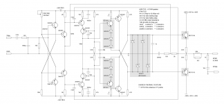
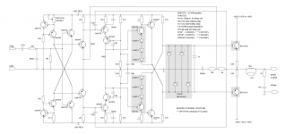
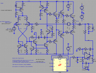
Here is the clipping behaviour of the CFA. (150% nominal input)
Pix 1: Note that the input stage (VAS input) never cut off (pink and green traces), and the cascodes saturates (dark red and yellow traces) limiting the excursion of OPS voltage to rail (red and blue traces) - 2.6V, so OPS never cut off, and leaves a Vce of 2.6V guard to avoid OPS instability. The output is the violet trace.
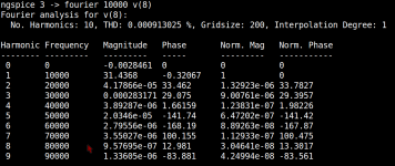
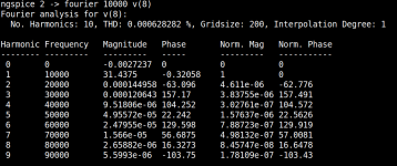
Pix 2: Show the symmetry 0.002 DC OFFSET and all distortion are due odd harmonics, leaving the clipping state is free from transients, clipping at 400KHZ or above shows a little (not oscillating) transient when re entering the linear region.
Cheers
Arturo


Here is the clipping behaviour of the CFA. (150% nominal input)
Pix 1: Note that the input stage (VAS input) never cut off (pink and green traces), and the cascodes saturates (dark red and yellow traces) limiting the excursion of OPS voltage to rail (red and blue traces) - 2.6V, so OPS never cut off, and leaves a Vce of 2.6V guard to avoid OPS instability. The output is the violet trace.
Pix 2: Show the symmetry 0.002 DC OFFSET and all distortion are due odd harmonics, leaving the clipping state is free from transients, clipping at 400KHZ or above shows a little (not oscillating) transient when re entering the linear region.
Cheers
Arturo
Last edited:
how about "the Original" FeedForward?
collected a couple of posts, the sim files are available in the respective threads
collected a couple of posts, the sim files are available in the respective threads
I worked up this "current dumping" Black's Feedforward sim from the jaes paper - sized for a headphone load since I'm using a op amp model with ~30mA output current limit
playing with the signal level it appears that it has the annoying property of increasing distortion as output level is reduced - the max % distortion occurs when the output level just starts to use the "dumper" Q for appreciable load current
feedback is necessary to implement the accurate correction amplifier in Black's Feedforward - I don't believe you can easily combine the sim's op amp and unbiased Q to do better in a "pure negative feedback" topology - so the Feedforward idea is valuable if you insist on "Class C+A"
the shown 2 V sine has ~0.01% output distortion, with the distortion growing to ~0.05% at around 200mV drive
...
I grabbed Bob's example sim from the TPC/TMC debate in the Cordell Book thread http://www.diyaudio.com/forums/soli...lls-power-amplifier-book-119.html#post2413197
my poking at it seems to indicate that the distortion is limited by the slow output Q and simply can't be made much better by feedback - especially the THD 20KHz that Bob likes as a simple quality metric (at least without going deep into conditional stability territory with 3-rd order or higher loop gain schemes)
if you can't fix up a amp with more feedback then the other tool is Black's Error Feedforward - rare in audio because of the difficulties power output combiner but famous none the less due to Quad’s "Current Dumping" amplifier
a error feedforward amp is defined by having 2 independent power amp paths to control the output - and the consequent difficulty of combining the outputs without their mutual loading causing unwanted additional (destabilizing) feedback
The VanderKooy Lipshitz Error Feedforward paper http://quad405.com/jaes.pdf shows several schemes - "Current Dumping" actually wraps negative feedback around the "dumper" amp stage - but 2 other schemes are shown - I chose the Parallel Feedforward from their fig 4b - which doesn't intentionally add loop feedback to the main amp and the coupling through the output impedances of the amps is minimal when used with a frequency selective power combiner
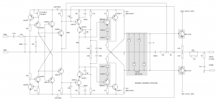
so the following is a Composite Amp using a large, slow discrete amp and a fast error feedforward op amp path
the instrumentation op amp measures the error at the diff pair input of the main amp with a gain of 10x, and then the CFA DSL driver op amp integrator provides the required error correction V drive for the Resistive leg of the L,R power output combiner network
Bob's THD 20KHz number is improved by ~20x in this sim
you will need Bob's zip file and to put my asc in the same folder with Bob's Cordell Models.txt file or you can download Bob's transistor models from his
book's site
Attachments
Hi jcx,
VanderKooy Lipshitz Error Feedforward paper completely unknown for me, after a brief reading I understand that the basic principle of this schema is adding a correction (from the auxiliary amp) 'feed forward' signal to the output of the main amp. to cancel the high order products that main amp would never be able to cancel, is this correct?. A question: the purpose of the CFA integrator is to correct the phase of the 'feed forward' signal to be in phase with main amp phase?
Cheers
Arturo
the "non-interacting" power output combiner is a difficulty
the L,R output combiner could be seen as a XO, the low frequency branch thru the output series L is driven by the main power amp
the fast correction amp path to the output through the resistor would be a 1st order highpass
but since the correction needs to add up to unity at the output you need a 1st order roll off for the correction amp's signal - hence the integrator
people like to draw the Quad Dumper circuit as a AC 4-arm bridge, the parallel circuit shown has a similar correction amp signal frequency shaping
I'm not yet really sure of the utility Black's Feedforward Error Correction scheme for audio power amps - except as a "band-aid" for being stuck with a poor performing main power amp
since you still have to accurately measure the error it seems like negative feedback around a better power amp would just be better
In the example of the BobAmp circuit I think doubling up ouput Q to avoid Beta droop and using 5x faster RET would let you get similar distortion improvement with 2-pole compensation
the Vanderkooy paper did suggest Black's Feedforward Error Correction as a way to help out Class D main power stages
Last edited:
jcx :
the "non-interacting" power output combiner is a difficulty
the L,R output combiner could be seen as a XO, the low frequency branch thru the output series L is driven by the main power amp
the fast correction amp path to the output through the resistor would be a 1st order highpass
but since the correction needs to add up to unity at the output you need a 1st order roll off for the correction amp's signal - hence the integrator
people like to draw the Quad Dumper circuit as a AC 4-arm bridge, the parallel circuit shown has a similar correction amp signal frequency shaping
I'm not yet really sure of the utility Black's Feedforward Error Correction scheme for audio power amps - except as a "band-aid" for being stuck with a poor performing main power amp
since you still have to accurately measure the error it seems like negative feedback around a better power amp would just be better
In the example of the BobAmp circuit I think doubling up ouput Q to avoid Beta droop and using 5x faster RET would let you get similar distortion improvement with 2-pole compensation
the Vanderkooy paper did suggest Black's Feedforward Error Correction as a way to help out Class D main power stages
Thank's for the explanation, not gone yet in deep, at first sight I guess Class D is the logic target for this kind of error correction, given that linear amps can achieve decent error correction by more simple means, unless "being stuck with a poor performing main power amp", and worth a 'minimal intervention' parallel aiding circuit. Anyway it's interesting for me as didn't see it before.
Cheers
Arturo
Hi Ontoaba,
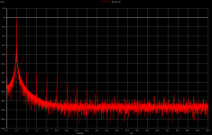
Nice to see you again, the CFA besides rock solid stability, it is amusing the high dynamic current capability it has, I didn't see in VFA this unique characteristic (maybe I am wrong), but in ie: at 20KHZ for 31W output at 8 OHM load (16 BJT schema) THD=0.00040%, then for 4 OHM load is 0.00043% and for 2 OHM load 0.00051, distortion is almost independent of high current load changes !!!, I really like it. About the bias, yes it can be set a little bit higher, anyway lot's of room for 'practical' experimentation.
Cheers
Arturo
Hi,Hi Ontoaba,
distortion is almost independent of high current load changes !!!,
Arturo
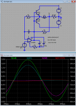
That load characteristics is very good to handle dynamic loads.
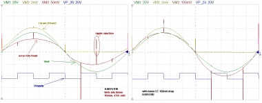
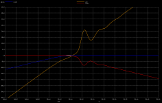
It may because it has linear drop voltage. (see picture for detail, it also show how stable they are when rejecting square supply ripple on HEXFETs output stage).
When entering unstable region, VFA input transistor one turned off and another one is saturated. This condition slightly degrade its performance and make VFA to have different speed and condition from classA to switching region.
While CFA still working in its safe conductivity, that is why it stay stable.
Also it has more linear drop voltages that make it able to have classA characteristics in beautiful 6kHz if used with current feedback without global voltage feedback.
Attachments
Last edited:
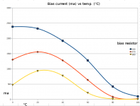
CFA output current bias
Another buffer configuration with a less stepper temperature profile (2 diodes+1 OHM resistor string) for different bias resistors. The quiescent current will be set by the heatsink temp, so it will be adjusted depending on ambient temperature.
Cheers
Arturo
Another buffer configuration with a less stepper temperature profile (2 diodes+1 OHM resistor string) for different bias resistors. The quiescent current will be set by the heatsink temp, so it will be adjusted depending on ambient temperature.
Cheers
Arturo
Attachments
Kenpeter....
I relally like your non switching diode idea....
what if the output stage was made with 2 lateral fets running some class A (like 200mA) and then followed by some bjt's wired up in your non switching manner as current dumpers...
Class A + nonswitch diode dumpers? Sounds plausible...
I'm not sure what advantage, since nothing this scheme
ever turns off or entirely leaves class A anyway?
You can up the bypass resistor to 200mA no prob...
I might already have it that high. Like I said earlier,
I've lost that .asc and would have to re-draw it to
rediscover what the bias points were.
5.1 ohm + 2n5551/5401 circuitry
Is optional, changes a bit the fft profile and reduces a bit distortion specially below 20KHZ at high amplitudes output. It is a local Feed Forward positive FB current aid (abusing rock solid stability). H3 is ~3 times lower at expenses of raising a little bit H2 and others, It maybe don't worth at those levels of distortion, who knows?
Cheers
Arturo
Umm, but what is that 2n5551/5401 with 5.1ohm Rbe used for?
Is optional, changes a bit the fft profile and reduces a bit distortion specially below 20KHZ at high amplitudes output. It is a local Feed Forward positive FB current aid (abusing rock solid stability). H3 is ~3 times lower at expenses of raising a little bit H2 and others, It maybe don't worth at those levels of distortion, who knows?
Cheers
Arturo
Attachments
Ken...
What happens when you really push it..I tried the wire something like yours up.. and at low voltage swings the output currents never goes lower than 50 mA, but when I let the amplifer sving 50 V.. (60V rails)...they go down to 0 mA...
Either half Schottky diode stack could be tricked to shut off if you clip hard
enough. But quiescent bypass current across sliding bias never shuts off.
The output devices remain always on at least this much...
Not worried a class B Schottky might shut off to keep a slower and uglier
device from doing so. Its all part of the design...
Quiescent current doesn't usually flow through load. Makes no difference
to the load that it flows in a bypass path not directly coupled to the load.
But makes a huge difference to the output devices that the load cannot
ever steal away this minimal bias current.
If I were to directly couple the small Class A bypass bias current to the
load, would defeat purpose of maintaining Class A in even the worst case.
Serious problem for amps with two resistors and ugly load in the middle...
I had some shutoff problems with complementary Aleph style outputs,
but was just due currents pumping into its own bootstaps. The topology
as shown, needs no bootstraps for an almost rail to rail output.
Last edited:
Quiescent current doesn't usually flow through load. Makes no difference
to the load that it flows in a bypass path not directly coupled to the load.
But makes a huge difference to the output devices that the load cannot
ever steal away this minimal bias current.
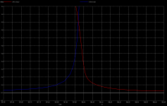
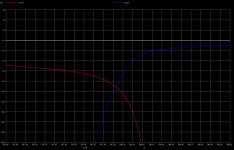
But quiescent current sets the output impedance seen by the load at the cross over region (which is short but not negligible). It can rise to near 1KOHM (pix 1) when OP currents overlap at ~8ma Class B (pix 2), this can make a big difference for the reactive currents flowing through the load. On the other side Class A is free from this impedance discontinuity, it always have a smooth drive over the load. I believe this lack of drive transient is what make the difference in sound that Class A folks claim.
Cheers
Arturo
Attachments
Voltage feedback sets output impedance. Quiescent current is a red herring.
The load has no clue whether any quiescent current is coupled to it or not.
Maybe in a current feedback amp things work different?
I do believe in a reasonable current minimum at all times including quiescence.
But that philosophy is merely to keep slow recovery devices from turning off.
The load has no clue whether any quiescent current is coupled to it or not.
Maybe in a current feedback amp things work different?
I do believe in a reasonable current minimum at all times including quiescence.
But that philosophy is merely to keep slow recovery devices from turning off.
Last edited:
Voltage feedback sets output impedance. Quiescent current is a red herring.
The load has no clue whether any quiescent current is coupled to it or not.
Maybe in a current feedback amp things work different?
That's AC analysis, I was digging the transient when there is almost no current flowing by both OP devices, are barely conducting or cut-off driving a more or less 'reactive load', showed in the pix, an extreme Class B 3OHM || 1n load (currents red, blue and output voltage yellow), there is no enough drive to handle reactive transient current at the load, output impedance is 3 orders of magnitude bellow load, maybe I'am wrong ???
Attachments
I do believe in a reasonable current minimum at all times including quiescence.
But that philosophy is merely to keep slow recovery devices from turning off.
Yes both OP devices cut-off for a period of time (Class C) implies a floating node end at the load ('infinite' impedance, maybe several KOHM's), if there is any reactive energy stored by the load will raise a big voltage transient that may reach the FB path if not properly isolated from the load.
- Status
- This old topic is closed. If you want to reopen this topic, contact a moderator using the "Report Post" button.
- Home
- Amplifiers
- Solid State
- Alternative topologies