Hi,
two of these, one on top of the other will increase dissipation by about 40%.
Two side by side or back to back will increase dissipation by ~100%.
Side by side spaces the FETs too far apart.
Back to back with the sinks clamping the devices would work if this is the top most part of the amplifier.
Two channels at full bias would probably require 4 of those sinks.
I didn't think they would have the data but they have. Well done MODU.
The data (which is attached) for a heatsink 400x 160x 40, (which means two of the 200x160x40 bolted to a joining bracket), at 25 degrees C ambient and Rt((degrees C/W) of 0.23.
For a TO3-P device, multiplied by 6, Max power dissipation (6xTO3-P) is 375W per heatsink.
The data (which is attached) for a heatsink 400x 160x 40, (which means two of the 200x160x40 bolted to a joining bracket), at 25 degrees C ambient and Rt((degrees C/W) of 0.23.
For a TO3-P device, multiplied by 6, Max power dissipation (6xTO3-P) is 375W per heatsink.
Attachments
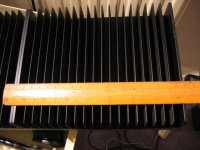
Having looked through Farnell heatsinks I have found one that looks very similar to those on the other chassis I was hoping to use for the amp.
This chassis has smaller heatsinks than the MODU design, measuring 300 width, 120 depth and 40 height similar to Forsman's.
I am getting a K/W of about 0.35 for this heatsink, looking at the graph supplied on the datasheet from Farnell.
This chassis has smaller heatsinks than the MODU design, measuring 300 width, 120 depth and 40 height similar to Forsman's.
I am getting a K/W of about 0.35 for this heatsink, looking at the graph supplied on the datasheet from Farnell.
Max power dissipation (6xTO3-P) is 375W per heatsink.
Sorry Andrew. I was writing down what was on the MODU datasheet without understanding it. I don't know where the 375W comes from.
Let me put it another way. If I put the BA-2 Mosfets on this heatsink will it cope because I thought that we were looking for about 75W dissipation?
Best wishes,
Chris
Let me put it another way. If I put the BA-2 Mosfets on this heatsink will it cope because I thought that we were looking for about 75W dissipation?
Best wishes,
Chris
I think my heat sinks are 0.4 C/W. If I understand the BA2 article correct each channel has 6 FETs and dissipates about 150 W per channel.
My heat sinks will then be 150 * 0.4 + 30 = 90 C which is 25 degrees higher than what Mr. Pass recommends (if I got it right).
Kind regards
/Forsman
My heat sinks will then be 150 * 0.4 + 30 = 90 C which is 25 degrees higher than what Mr. Pass recommends (if I got it right).
Kind regards
/Forsman


At Pass Laboratories read the A75 part 2 article. There is a good discussion of how to calculate how much heat sink you'll need. It boils down to adding thermal resistances, multiplying the sum by the power dissipated to determine the temperature rise. Given a temperature rise of 30C, you can rearrange the equation to determine the needed heat sink thermal resistance. There are other places on the web that present it differently if you cannot wrap your head around Papa's explanation. Rod Elliot's site and the LM3886 data sheet are two I know of.
- Home
- Amplifiers
- Pass Labs
- Burning Amplifier BA-2