When I said all the grounds of rectifier and caps, I meant per channel of course.
Sorry couldnt edit on my ipad...
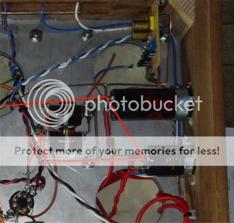
And do i see this correct? Are your big powersupply caps grounds connected to each other AND both to the starground? If so, start with cutting the connection from the cap closest to the rectifier. The ground to starground connection that is....
Sorry couldnt edit on my ipad...
And do i see this correct? Are your big powersupply caps grounds connected to each other AND both to the starground? If so, start with cutting the connection from the cap closest to the rectifier. The ground to starground connection that is....
Last edited:
I can't see the diodes in the picture. Anyway, if the diodes for each channel are connected directly to the reservoir capacitor -ve for each channel (the correct wiring for separate secondaries) then this could be the source of the hum. Remember that the common secondary and the common star point mean that the two diodes conducting (one per channel) are connected in parallel. They won't be perfectly matched so one diode will take most of the current. This means that the ground connection between the two reservoir caps will carry ripple current. On the opposite cycle it may go the same way or the other way, depending on the diode matching/mismatching. These two ground connections are thus dirty and must not be used for anything else. You seem to use them to connect to the -ve on the smoother cap for each channel. Thus you are injecting ripple into the smoother cap ground. Bad hum is inevitable.
You need to rethink your grounding. Think about where the currents go. Regard each piece of ground wire as having a significant resistance across which a current will generate a voltage. Also, the +ve lead to the reservoir caps should follow the -ve lead so it minimises the loop area enclosed by charging pulses.
Hi DF96
I think you are on to something here. I have a sence this could be the problem, I don´t understand why but in a strange way it seems right. I will try to check this when I get the new ECC99´s.
Cheers
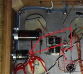
Oh I forgot, very neat and clean build! Really nice! How does the outside look?
Picture?
Thank you pauldune
Here are some pictures. The chassis is made from 150 year old mahogany that once was the decking on a sailingship called Pommern. The wood is really hard and dence. The stainless steel top is 3 mm thick! The whole amp weighs in at 55kg, 120 lbs.


Cheers
I can't see the diodes in the picture. Anyway, if the diodes for each channel are connected directly to the reservoir capacitor -ve for each channel (the correct wiring for separate secondaries) then this could be the source of the hum. Remember that the common secondary and the common star point mean that the two diodes conducting (one per channel) are connected in parallel. They won't be perfectly matched so one diode will take most of the current. This means that the ground connection between the two reservoir caps will carry ripple current. On the opposite cycle it may go the same way or the other way, depending on the diode matching/mismatching. These two ground connections are thus dirty and must not be used for anything else. You seem to use them to connect to the -ve on the smoother cap for each channel. Thus you are injecting ripple into the smoother cap ground. Bad hum is inevitable.
You need to rethink your grounding. Think about where the currents go. Regard each piece of ground wire as having a significant resistance across which a current will generate a voltage. Also, the +ve lead to the reservoir caps should follow the -ve lead so it minimises the loop area enclosed by charging pulses.
Hi DF96
Is there a reason for the diodes to be connected to the reservoir caps or could the go directly to ground instead? I mean so that the diodes and caps dont share the same ground lead.
Im no technichian and have only basic understanding so Im struggling a bit here.
Cheers
Last edited:
Hi DF96
I think you are on to something here. I have a sence this could be the problem, I don´t understand why but in a strange way it seems right. I will try to check this when I get the new ECC99´s.
Cheers
Hi DF96
Is there a reason for the diodes to be connected to the reservoir caps or could the go directly to ground instead? I mean so that the diodes and caps dont share the same ground lead.
Im no technichian and have only basic understanding so Im struggling a bit here.
Cheers
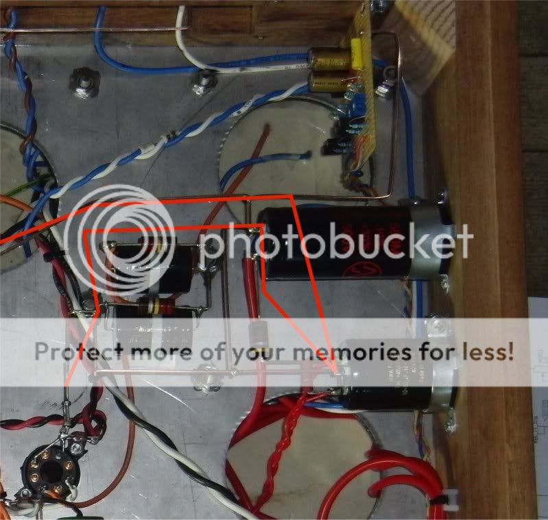
No they should be connected to the cap, and in my opinion, the only connection from powersupply chain (xformer, rect, cap, choke, cap) to star ground should be at the last cap. The one closest to the ampifiercircuit, the same one you pull b+ from...
But really look good at your grounding across the caps, I can see two loops already. (as i tried to exlain earlier). Maybe I wasnt clear? Its often difficult to rephrase my thoughts in english....sorry for that.
DF96
Would this be worth trying?
Would this be worth trying?
An externally hosted image should be here but it was not working when we last tested it.
DF96
Would this be worth trying?
An externally hosted image should be here but it was not working when we last tested it.
No! Did you read anything i wrote?
The problem isnt in the schematic, its in how you build it. All grounds are connected.always.
But sometimes you have to split them up, and make 2 or more star grounds in an amplifier. But there always remains a connection between them so they have to same potential (v)
Last edited:
No they should be connected to the cap, and in my opinion, the only connection from powersupply chain (xformer, rect, cap, choke, cap) to star ground should be at the last cap. The one closest to the ampifiercircuit, the same one you pull b+ from...
But really look good at your grounding across the caps, I can see two loops already. (as i tried to exlain earlier). Maybe I wasnt clear? Its often difficult to rephrase my thoughts in english....sorry for that.
pauldune
Like this?
Or like this
The grounding going of to the right goes to the bias supply. I guess this should have a separate ground going to star ground.
Last edited:
Come to think of it the groundwire from the bias supply is possitive and connected to ground at the 500uf cap. Could this be the reason for hum? Maybe the bias supply should have a separate grounding to star ground??
Cheers
No definitely not! if the positive of the bias supply isnt grounded, it has no reference to ground, ie it wouldnt be a negative voltage, which is required for biasing, so it must be grounded.
You should give it a direct connection to star ground, however, only one per side, and only from cap ground to star ground.
like the pic im going to attach in the next post that is an answer to your earlier post

pauldune
Like this?
pic
Or like this
pic
The grounding going of to the right goes to the bias supply. I guess this should have a separate ground going to star ground.
No I would do it like this...
ps I dont see the silicon rectifiers in your fotos, I assume they are somewhere hidden near the tube rectifier....
Attachments
I guess your second drawing pictured more or less the same, but you should indeed give the bias pcb its own connection to star ground...
Youre right, I understand that the cap nearest to amp circuit is to be grounded to star ground, in this case the lower double cap in the picture.
Here are the diodes
An externally hosted image should be here but it was not working when we last tested it.
Ok, so the bias supply is crucial, I will give the bias supply it´s own ground to star ground.
Cheers
Last edited:
You've got a pretty hefty gnd-bus. I am skeptical star gnd will make such a difference.
Can you try to place a cap to gnd from the output stage's input, to see if hum goes away? that way you can eliminate the hum source a little. If the hum dissapears when the output tube's grids are shunted to gnd via the cap, then the hum is produced further up in the voltage gain stage. You can then go further up and eliminate stage by stage.
The output stage is symmetrical, and unlikely source of hum. Allthough the ungrounded heaters to the output tubes may do something???
The input and diff stage are both unsymmetrical and may introduce hum from ripple, but you should have very little ripple with that supply.
Anyhow, good luck, you've got to get this nice construction up and running.
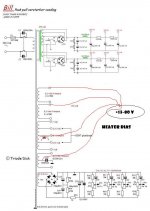
Here is what I mean by heater bias:
Can you try to place a cap to gnd from the output stage's input, to see if hum goes away? that way you can eliminate the hum source a little. If the hum dissapears when the output tube's grids are shunted to gnd via the cap, then the hum is produced further up in the voltage gain stage. You can then go further up and eliminate stage by stage.
The output stage is symmetrical, and unlikely source of hum. Allthough the ungrounded heaters to the output tubes may do something???
The input and diff stage are both unsymmetrical and may introduce hum from ripple, but you should have very little ripple with that supply.
Anyhow, good luck, you've got to get this nice construction up and running.
Here is what I mean by heater bias:
Attachments
1. Get rid of one pair of silicon rectifiers. There is no point in paralleling them.
2. Connect the -ve of the two reservoir capacitors directly together.
3. Connect the 'ground' connection of the diodes to somewhere on this -ve link.
4. In one channel, connect the diode ground point to the smoother -ve and then from there to the star. In the other channel, just connect the smoother -ve to the star.
5. The bias supply should be grounded to the star (at the bias supply output only - you don't want to inject bias rectifier ripple into the ground).
You then have the output of your dual PSU connected to the star. Charging pulses are kept away from the star. You still have a minor problem of smoothed ripple from one channel appearing in a ground connection for the other but I don't know how to avoid that with two PSUs driven from one secondary. Personally, I would either change the transformer to have separate secondaries, or make a proper combined PSU (which could still have separate smoothing/decoupling for the earlier stages). You seem to be trying to change horses in midstream!
Remember the golden rules:
- each grounded point (or bus) should have one and only one ground connection (no loops),
- a ground connection should carry signal or PSU currents, never both (no noise injection).
- a ground connection should carry input or output currents, never both (no unplanned feedback).
or make a proper combined PSU (which could still have separate smoothing/decoupling for the earlier stages).
This is worth a try, since it's so easy. Along with the other suggestions above, simply connect the 470V B+ from each supply together. I've never found much benefit to separate supplies for each channel in a stereo amp with adequate filtering.
Sheldon
I guess your second drawing pictured more or less the same, but you should indeed give the bias pcb its own connection to star ground...
Ok, new drivertubes 12BH7 instead of ECC99.
Ok, I re wired the ground and I now have no loops and last cap in PS goes to star ground. I also gave the bias supply it´s own ground lead to star ground.
Turned the amp on and now I really have hum, BIG LOUD HUM!! I measured the output speaker jacks and I have 1,5VAC and 2,33VAC on them?
Only good news is that the problem seems to be in the PS
Something is really wrong in the PS but I can´t se anything wrong. Maybe it has something to do with the diodes?
Cheers
Last edited:
What exactly have you done? "Rewired the grounds" is too vague. The sort of hum you are getting strongly suggests that you are injecting ripple into a signal ground.
I suggest you redraw the circuit diagram, showing the grounding as it actually is. Include the safety ground too, as that might be relevant.
I suggest you redraw the circuit diagram, showing the grounding as it actually is. Include the safety ground too, as that might be relevant.
- Status
- This old topic is closed. If you want to reopen this topic, contact a moderator using the "Report Post" button.
- Home
- Amplifiers
- Tubes / Valves
- Anyone care for some troubleshooting? Hum issue