Thanks Atmas for the circuit, very interesting. It is, of course, basically a redrawing of the totem pole circuit, with the need for two fully floating indepedent supplies for the output valves. It does, however, seem to simplify the drive requirements a bit, so that helps.
I've seen this somewhere in a solid state design but don't remember where.
The output impedance for totem pole and cyclotron will be the same, and in the case of valves output power will be entirely dependent on the valve peak current ability.
However as power is I squared times ohms, then doubling the valve count will quadruple the power output (to a point).
The 2 valve version will just manage 5 W peak, 2.5 W RMS.
The 4 valve will do almost 4 times that, ie nearly 20 W peak, 10 W RMS
And so the 8 valve version 4 times that? Well no actually. As the output voltage swing increases, this removes the available voltage across the valves themselves so they are capable of delivering less current, so for the 8 valve we are dowm to 60 Watts peak, which for us is 30 Watts RMS.
Now we have a stereo amp delivering 30 W per channel running 16 6AS7G's on full tilt.
You'll want to turn that radiator off, even in this weather.
Interesting to note that as the output falls with increasing output volts, this is negative feedback at work so the output signal won't be quite so dependent on varying speaker load impedance.
It still will be, but not as bad as if from a true current source.
If you want to find out in advance what it will sound like then that's quite easy.
Use your normal transistor amp setup, and add a resistor (say 80 to 100 ohms, 10 watt) is series with the speaker.
Of course the output will be much reduced, but you will hear the effect of the varying load impedance has on the performance.
Perhaps you don't have to bother to built the valve OTL after all.
Right, must now go and get some work done.......
The 6AS7G (6080) is rated to run at 125mA, that means it's happy with peaks up to 250mA. All well made valves have a fair bit of surplus built in to cope with ageing, so with the sails up and a good following wind you might just get 400mA peak. With both sections strapped together that gives you 800mA peak. Across an 8 ohm load that translates to 5 Watts peak. It's still only 2.5 Watts RMS.
Perhaps Atmasphere you'd like to share you circuit with the rest of us.
Regards
Henry
Using only 125 plate volts, I get about 500mA peak per triode out of these tubes. When driving the grids positive with a MOSFET follower I get just under 1amp!
Well done Semper. 400 to 500 mA peak is very much the same ball park, and these peak outputs will be very much dependent on the manufacturer and date of manufacture etc.
All of the discussions so far have been with normal drive levels, ie high impedance source, and not driving positively and drawing grid current.
Adding all these things is rather going away from the original thread of not getting too complicated.
All of the discussions so far have been with normal drive levels, ie high impedance source, and not driving positively and drawing grid current.
Adding all these things is rather going away from the original thread of not getting too complicated.
Why thank you. To be honest I've pretty much skipped this thread so not surprised I'm going off topic, but noticed your post on output current from the 6AS7 and figured I'd mention my findings.
I do use normal drive levels tho and normally I don't use a follower to drive the grids positive.
I do use normal drive levels tho and normally I don't use a follower to drive the grids positive.
Thanks Atmas for the circuit, very interesting. It is, of course, basically a redrawing of the totem pole circuit, with the need for two fully floating indepedent supplies for the output valves. It does, however, seem to simplify the drive requirements a bit, so that helps.
I've seen this somewhere in a solid state design but don't remember where.
The GAS amplifier used a similar setup. It is worthy of note that the Circlotron is **not in any way** a redrawing of a totem-pole. This can be seen by the fact that the cathodes of both push and pull are driving the load while the plates of each are tied to their power supplies.
The output impedance for totem pole and cyclotron will be the same, and in the case of valves output power will be entirely dependent on the valve peak current ability.
The output impedance of a Circlotron tends to be 1/2 that of a totem-pole circuit.
However as power is I squared times ohms, then doubling the valve count will quadruple the power output (to a point).
The 2 valve version will just manage 5 W peak, 2.5 W RMS.
The 4 valve will do almost 4 times that, ie nearly 20 W peak, 10 W RMS
And so the 8 valve version 4 times that? Well no actually. As the output voltage swing increases, this removes the available voltage across the valves themselves so they are capable of delivering less current, so for the 8 valve we are dowm to 60 Watts peak, which for us is 30 Watts RMS.
Now we have a stereo amp delivering 30 W per channel running 16 6AS7G's on full tilt.
You'll want to turn that radiator off, even in this weather.
Interesting to note that as the output falls with increasing output volts, this is negative feedback at work so the output signal won't be quite so dependent on varying speaker load impedance.
It still will be, but not as bad as if from a true current source.
If you want to find out in advance what it will sound like then that's quite easy.
Use your normal transistor amp setup, and add a resistor (say 80 to 100 ohms, 10 watt) is series with the speaker.
Of course the output will be much reduced, but you will hear the effect of the varying load impedance has on the performance.
Perhaps you don't have to bother to built the valve OTL after all.
Right, must now go and get some work done.......
I'm guessing that you are using some assumptions above that are incorrect. With eight 6AS7Gs (which is 16 sections) the amplifier can make 60 WRMS into 8 ohms. It will make about 80 WRMS into 16 (and will also run cooler as the output section becomes more efficient), but as impedance is increased above that the power will start to drop off slowly.
The sounds is *quite* different from putting a resistor in series with a solid stage amplifier. It is quite lively and transparent, yet also very relaxed as open loop distortion is rather low.
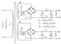
Given that the circuit drawing is incomplete I did have to make one assumption. That where is written Bridge1(+) etc. these are the power supplies for the output valves, namely a secondary winding of a transformer, a bridge rectifier and a largish reservoir capacitor.
This capacitor is thus connected from the anode of one valve to the cathode of the other, and from the ac standpoint it doesn't matter whether the load is connected from cathode to cathode or anode to anode or indeed from anode to cathode (given a DC blocker).
If you now only draw the valves and the caps you will see the ring (hence cyclotron) of valve/cap/valve/cap.
This is easily redrawn to be valve/valve/cap/cap, and so we are back to the totem pole, with the same output impedance.
There is no current through the 'ring'. It is well-know that Circlotrons are quite different from totem poles. There are two secondaries on the power transformer, each supplying identical supplies.
There is a discussion about the capacitors in the power supplies that starts on this page of this thread:
http://www.diyaudio.com/forums/tube...mplifier-only-3-components-signal-path-2.html
There is a discussion about the capacitors in the power supplies that starts on this page of this thread:
http://www.diyaudio.com/forums/tube...mplifier-only-3-components-signal-path-2.html
There is quite a nice discussion by John Broskie, on his website at John Broskie's Guide to Tube Circuit Analysis & Design, in an article called "Cars, planes and circlotrons." Viewing the power supplies as being dead shorts as far as AC is concerned, he makes the point that a circlotron and a totem pole configuration are not so very different. What is different, as far as I understand it, is how the driving signals for the output tube grids are referenced. In a circlotron, there is a complete symmetry between the way the tubes in the two banks are driven. In a conventional totem pole configuration, by contrast, the upper tube(s) is working like a cathode follower, and the lower like an anode follower. This is because the signal to the upper tube is effectively, as far as AC is concerned, between grid and anode, whereas for the lower tube, the signal is effectively between grid and cathode.
John Broskie has a schematic (labelled (c) in the set of 6 schematics on page 16 of his article) which is a totem-pole that seems to be essentially symmetric, as far as AC is concerned, and which I think he would claim to be equivalent to the circlotron. As he says, a tube doesn't "know" whether it is a cathode follower or whatever, it just knows about the voltages between its various electrodes. It seems to be true that even though his schematic (c) doesn't look manifestly symmetric, as far as the AC signals are concerned it would behave the same as the circlotron.
Of course it would be somewhat perverse actually to build his schematic (c), since it would still need the separate power supplies for the right and left channels, and one might as well in that case go for the true circlotron.
And I think it is still the case that if the grounding is done in the "conventional" way for a totem pole (i.e. one speaker terminal grounded), then it does operate asymmetrically, with one tube a cathode follower and the other an anode follower.
Chris
Many thanks to Chris for his contribution. John Broskie's article is brilliant, couldn't have written it better myself.
So now over to StoneT to build one of the amps, no output transformers but a whole stack of power transformers. And those capacitors for the output stages, what to go for?, no mention anywhere of what they should be.
Lets start with a minimum of 4700uF at 160 Volts, oh and for good measure they should be LoZ types and 105degree with alll that heat floating about.
Comments welcome
Greetings to all
Henry
Lets start with a minimum of 4700uF at 160 Volts, oh and for good measure they should be LoZ types and 105degree with alll that heat floating about.
Comments welcome
Greetings to all
Henry
I sugest You to use two 4700uF/200 V DC for output power stage 2x140V V/DC floathing PSU ,since 4700uF with 160V/DC ratings is very close to 140 V/DC rail voltage .
Some `healty` capacitors breakdown voltage reserve have to be have Allways for those PSU Elko Capacitors.
Here is My litlle modified output power(Circlotron) PSU schematic.
Important: This two 140V/DC PSU minus output to NOT tight anywhere to the ground point !They have to be stay Independent and Floathing with respect to ground point.
105 degree temperature ratings is good choice.
Best Regards to All
")
Attachments
Last edited:
Over the last 35-some years, I have had a lot of people ask me if our amplifier was a Futterman. The Futterman used the totem-pole output. They also tended to be unstable, apparently, as I was often asked if our amplifier would blow up. We use it as a guitar amplifier- it does not do that. If the Futterman was built right, it would not blow up either, although many succeeding iterations that occurred after Futterman's death did.There is quite a nice discussion by John Broskie, on his website at John Broskie's Guide to Tube Circuit Analysis & Design, in an article called "Cars, planes and circlotrons." Viewing the power supplies as being dead shorts as far as AC is concerned, he makes the point that a circlotron and a totem pole configuration are not so very different. What is different, as far as I understand it, is how the driving signals for the output tube grids are referenced. In a circlotron, there is a complete symmetry between the way the tubes in the two banks are driven. In a conventional totem pole configuration, by contrast, the upper tube(s) is working like a cathode follower, and the lower like an anode follower. This is because the signal to the upper tube is effectively, as far as AC is concerned, between grid and anode, whereas for the lower tube, the signal is effectively between grid and cathode.
John Broskie has a schematic (labelled (c) in the set of 6 schematics on page 16 of his article) which is a totem-pole that seems to be essentially symmetric, as far as AC is concerned, and which I think he would claim to be equivalent to the circlotron. As he says, a tube doesn't "know" whether it is a cathode follower or whatever, it just knows about the voltages between its various electrodes. It seems to be true that even though his schematic (c) doesn't look manifestly symmetric, as far as the AC signals are concerned it would behave the same as the circlotron.
Of course it would be somewhat perverse actually to build his schematic (c), since it would still need the separate power supplies for the right and left channels, and one might as well in that case go for the true circlotron.
And I think it is still the case that if the grounding is done in the "conventional" way for a totem pole (i.e. one speaker terminal grounded), then it does operate asymmetrically, with one tube a cathode follower and the other an anode follower.
Chris
There was another peculiarity: The Futterman amplifiers always seemed to make their power into loads that were higher impedance. A drop in output power was always seen going into 8 ohms or less. By comparison of output power, this was not the case with the amplifiers I was working with (Circlotrons). They tended to loose less power or none at all, despite being lower powered amplifiers and zero feedback.
So if I could characterize the difference between the two circuits, it would be this: 1) the circuit has 1/2 the output impedance, 2) it allows for symmetrical drive, which is another way of saying you can keep the circuit simple.
I have measured the distortion of the circuit and it generates primarily a 3rd harmonic.
The TubeCad article has had some incorrect assumptions (ex.: there is a reference to the plate voltages dropping, which does not happen in the circuit) as far as I could ever tell, nor does it appear that the author ever owned a set of Atma-Sphere M-60s as he claimed (we would have known about that at the time...). While PSpice is a useful tool, anyone working with actual circuits has bumped into its limitations more than once.
The reason the Circlotron has 1/2 the output impedance is simply that both tubes have 100% feedback. In a totem pole, only one tube has this advantage. If you use a tubes with a low mu, this advantage is eroded.
Several people have commented that the tubecad article claims that class A is not possible with a Circlotron but I don't see that in the text. What I do see is some snide innuendo, although it hard to say why or where its directed.
The TubeCad article has had some incorrect assumptions (ex.: there is a reference to the plate voltages dropping, which does not happen in the circuit) ...
The context in the TubeCad article where Broskie talks about the plate voltage dropping is where he is carrying out a "thought experiment" to investigate the response of the amplifier to an applied external voltage across the output terminals. (As a way of "measuring" the output impedance.) He is viewing this as a "virtual" process, I think, in which one first imagines what happens when the external voltage is applied, but the tubes have "not yet" responded to the consequently changed grid-cathode potential. The second step is to see what the effect of the changed grid-cathode potential will be; namely a tendency to oppose the originally applied external perturbation to the system. As a heuristic way of discussing the response of the system to a perturbation, whilst avoiding the need for a full-blown mathematical analysis, it seems to me it captures the essence of what is going on.
Given that context, it seems to me that what he is saying about plate voltages going up and down is surely correct. All his voltages are measured with respect to ground, and the power supplies are assumed to be ideal constant-voltage sources. In the circlotron, one end of each power supply is connected to an output terminal, and the othe end to a plate. Thus, if the output terminal voltage is displaced downwards by 1 V, i.e. from 0 V to -1 V, then the corresponding plate voltage will be displaced downwards by 1 V also (from 100V to 99 V in his toy example where the power supplies are taken to be 100 V each). This is the "plate voltage dropping" that he is referring to.
In any case, in actual operation as opposed to the above thought experiment, the plate voltages in the circlotron (measured with respect to ground) will certainly be going up and down, since the plate voltage is equal to the sum of the (essentially constant) power supply voltage plus the voltage on the corresponding output terminal. Neither output terminal is grounded, and so the voltages on the two output terminals are going up and down in antiphase, as a consequence of the signal being amplified. These oscillatory voltages are then transferred, with the addition of the (constant) power supply voltages themselves, to the plates.
Chris
I always recommend to people to try the circuit out first. And then take a look at the way the currents flow in the circuit. It amazing how much less of this sort of conversation occurs when there is experience with the circuit.
It is as he says though, nothing magical... but OTOH it also does behave according to physical laws. For example, the power supplies behave in the circuit in much the same way that they do in a single-ended amplifier.
What you see is that the plate of the tube is really a fairly constant voltage- and the more one can do to reduce any noise in the supply the better. The difference between the grids and the cathodes is where the action is. The tubecad article is not based on actual circuit experience- its based on conjecture. For the most part, I enjoy his articles but as one might expect I differ with him on this one.
You do not want to measure the plate voltages with respect to ground since the power supplies are floating. This is a very common mistake! You measure them from the other side of the load from the B+ if you want an accurate reading.
Another common mistake is to use a 'scope to observe the output- unless the 'scope is also floating you will get a distorted reading as one side the amplifier will be grounded. It will look like gross 2nd harmonic distortion. Associated with that, another common measurement error is to have a dual-trace 'scope, with one trace set to the signal generator and the other to the 'scope probe at the output. Oops! The generator is at ground so now the 'scope is too. To solve this you sometimes need to use an input transformer to isolate the grounds.
What you see is that the plate of the tube is really a fairly constant voltage- and the more one can do to reduce any noise in the supply the better. The difference between the grids and the cathodes is where the action is. The tubecad article is not based on actual circuit experience- its based on conjecture. For the most part, I enjoy his articles but as one might expect I differ with him on this one.
You do not want to measure the plate voltages with respect to ground since the power supplies are floating. This is a very common mistake! You measure them from the other side of the load from the B+ if you want an accurate reading.
I think this is taking the discussion off onto tangential issues. The point of Broskie's discussion was NOT to address the question of how to measure the power supply voltages and to make sure they are behaving well. In fact, for his discussion, he assumed that the power supplies were ideal. It is of course true that if you wanted to check the characteristics of the power supplies,you would waant to measure directly between the + and - terminals of each power supply.
The point of his article was to discuss the theory of operation of a circlotron, vs. the theory of operation of a totem-pole configuration. Power supplies can be assumed to be perfect, for the purposes of this discussion. In order to study the theory of operation of the amplifiers, he finds it expedient to discuss all voltages with respect to ground. In the context of his discussion, I think this is quite reasonable. In particular, as he says, the plate voltages with respect to ground will rise and fall.
Chris
Perhaps then that is where his error in assumption occurs. If you look at voltages with respect to ground, you will not see how the circuit works. It takes some getting used to, but the circuit floats, so comments like the ones about the plate voltages varying go right out the window. If the circuit is working, the plate voltages don't move. If you refer to ground, all you do is create confusion, unless the circuit is at rest.
Over the last 35-some years, I have had a lot of people ask me if our amplifier was a Futterman. The Futterman used the totem-pole output. They also tended to be unstable, apparently, as I was often asked if our amplifier would blow up. We use it as a guitar amplifier- it does not do that. If the Futterman was built right, it would not blow up either, although many succeeding iterations that occurred after Futterman's death did.
There was another peculiarity: The Futterman amplifiers always seemed to make their power into loads that were higher impedance. A drop in output power was always seen going into 8 ohms or less. By comparison of output power, this was not the case with the amplifiers I was working with (Circlotrons). They tended to loose less power or none at all, despite being lower powered amplifiers and zero feedback.
So if I could characterize the difference between the two circuits, it would be this: 1) the circuit has 1/2 the output impedance, 2) it allows for symmetrical drive, which is another way of saying you can keep the circuit simple.
I have measured the distortion of the circuit and it generates primarily a 3rd harmonic.
The TubeCad article has had some incorrect assumptions (ex.: there is a reference to the plate voltages dropping, which does not happen in the circuit) as far as I could ever tell, nor does it appear that the author ever owned a set of Atma-Sphere M-60s as he claimed (we would have known about that at the time...). While PSpice is a useful tool, anyone working with actual circuits has bumped into its limitations more than once.
The reason the Circlotron has 1/2 the output impedance is simply that both tubes have 100% feedback. In a totem pole, only one tube has this advantage. If you use a tubes with a low mu, this advantage is eroded.
Several people have commented that the tubecad article claims that class A is not possible with a Circlotron but I don't see that in the text. What I do see is some snide innuendo, although it hard to say why or where its directed.
Disappointed to see the bit about snide innuendo, certainly none intended from here.
And none takenDisappointed to see the bit about snide innuendo, certainly none intended from here.
Hi Nelson!
Perhaps then that is where his error in assumption occurs. If you look at voltages with respect to ground, you will not see how the circuit works. It takes some getting used to, but the circuit floats, so comments like the ones about the plate voltages varying go right out the window. If the circuit is working, the plate voltages don't move. If you refer to ground, all you do is create confusion, unless the circuit is at rest.
I think one has to read Broskie carefully, to see what he is claiming and what he isn't. He is NOT saying that a standard totem-pole configuration behaves the same as a circlotron. What he IS saying is that whether you make the "daisy chain" ordering tube/psu/tube/psu, as in the circlotron,or instead the ordering tube/tube/psu/psu as in the totem-pole, makes, of itself, no essential difference. What DOES matter is where you tie the thing to ground. In the circlotron, it is effectively the mid-point between the two speaker terminals that is tied to ground. In a standard totem-pole configuration, one of the speaker terminals is tied to ground (the one connected to the midpoint of the two power supplies). This introduces the asymmetry, and the very real difference as compared with the circlotron operation.
Broskie presents 6 schematics in the diagram on page 16 of his article. Schematics (a), (c) and (e) are totem poles, with the ground being tied to the left-hand speaker terminal, the midpoint, and the right-hand speaker terminal respectively. Schematics (b), (d) and (f) are "circlotrons," with the ground being tied to the left-hand, the midpoint and the right-hand speaker terminals respectively.
Schematic (e) is the standard totem-pole, and schematic (d) is the standard circlotron. He is NOT saying that they are equivalent in their operation.
What he IS saying is that schematic (c), a "minor variant" on the totem-pole in which the midpoint between the two speakers terminals is instead grounded, is completely equivalent to the standard circlotron output stage. He gives general arguments for why that is so, and he also reports the results of PSpice simulations for schematics (c) and (d) that confirm this.
I don't think he is saying anything controversial, because the the "minor variation" of the totem-pole configuration that he makes means that it is NOT the circuit that anybody making a totem-pole OTL ever normally uses.
But the interesting observation that he makes is that it is the decision of what point to tie to ground that makes all the difference in the performance of the circuits, rather then the decision of daisy-chaining tube/psu/tube/psu vs. tube/tube/psu/psu.
Let me just add that I personally have built three OTLs, two of which are totem-poles ("standard" Broskie (e)-type!), and one circlotron. Of the three, I think I like the circlotron the most.
Chris
- Status
- This old topic is closed. If you want to reopen this topic, contact a moderator using the "Report Post" button.
- Home
- Amplifiers
- Tubes / Valves
- Push-Push OTL?